Rockwell Automation 8520 9/Series CNC Integration Maintenance Manual Documentation Set User Manual
Page 573
I/O Interface
Section 10A
10A-50
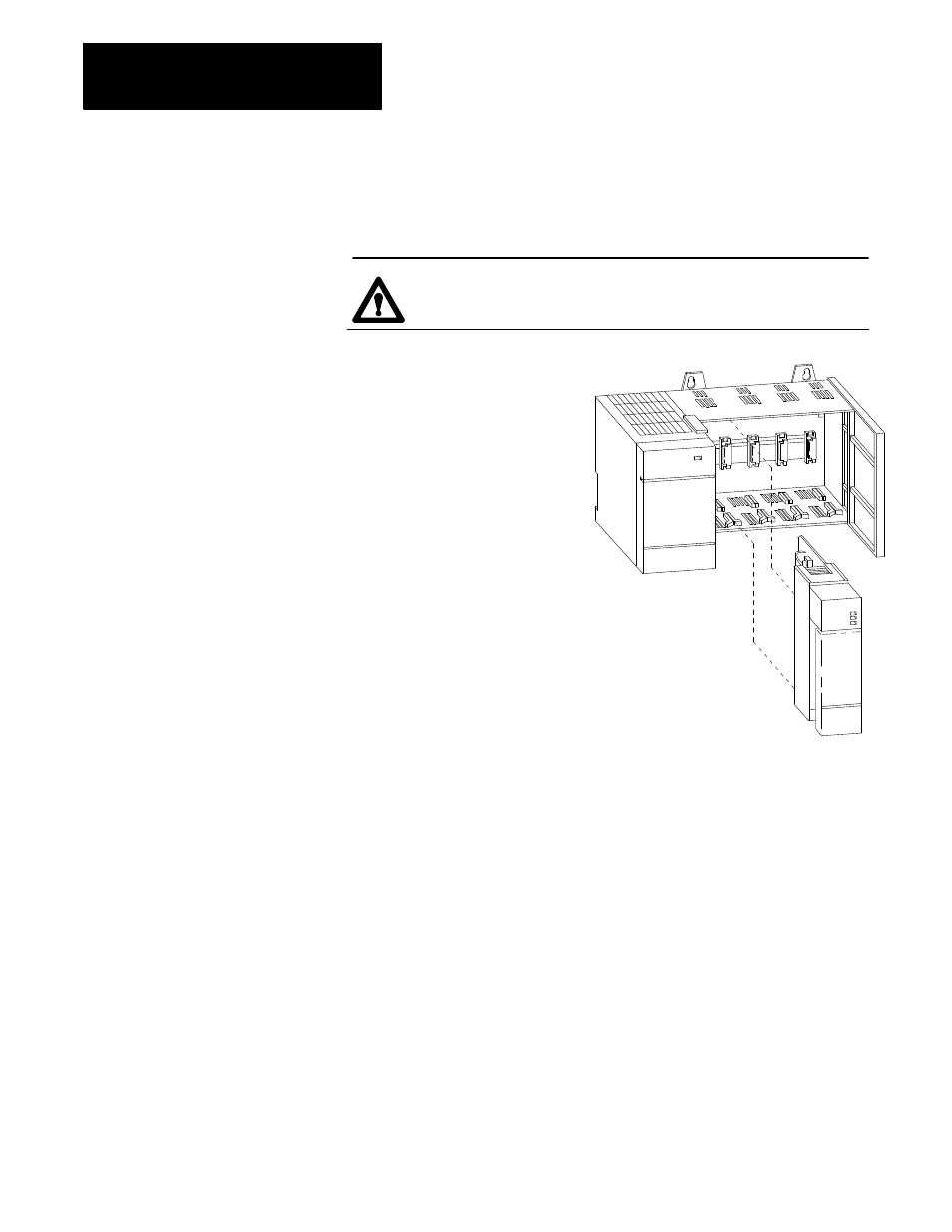
The following procedure covers how to remove modules from your 1746
I/O chassis. In some cases it is necessary to remove a module to set or
check dip switch settings.
ATTENTION: Never install, remove, or wire modules with
power applied to the chassis.
Removing a Module
1. Label and remove any wiring or removable terminal blocks.
2. Gently press in on both the top and bottom latches of the
module to be removed.
3. Slide the module out of the rack.
Installing a Module
1. Align the circuit board of the module with the card guide in
the chassis.
Important: You must install the 1746I module in the first slot of the
chassis (slot immediately next to the power supply). The 1746I module takes
the place of a CPU module or a ASB adapter module in this slot. Other modules
should be returned to the same slot they were removed from.
2.
Gently slide the module in until both top and bottom latches are
latched.
3.
Reconnect wires or removable terminal blocks.
Cover all unused slots with a Card Slot Filler, Catalog Number 1746-N2.
To install the 1746I module in the 9/Series I/O ring you must first assign
the module an address on the 9/Series I/O ring. If the module is already
installed in your 1746 I/O chassis, you must remove the module to set the
module address. Remove the module by pressing in on the locking tabs on
the top and bottom of the 1746I module and sliding the module out of the
chassis.
Assign an address to the module using the dip switch S1 found on the side
of the 1746I module. Figure 10B.4 shows the location of the node address
switch assembly on the 1746I module.
10A.6.1
Removing/Installing
1746 Modules
10A.6.2
1746I I/O Ring Adapter Node
Address Setting