Wiring a probe for rising edge configurations – Rockwell Automation 8520 9/Series CNC Integration Maintenance Manual Documentation Set User Manual
Page 195
Section 4B
Connecting the 3-axis Servo Module
4B-49
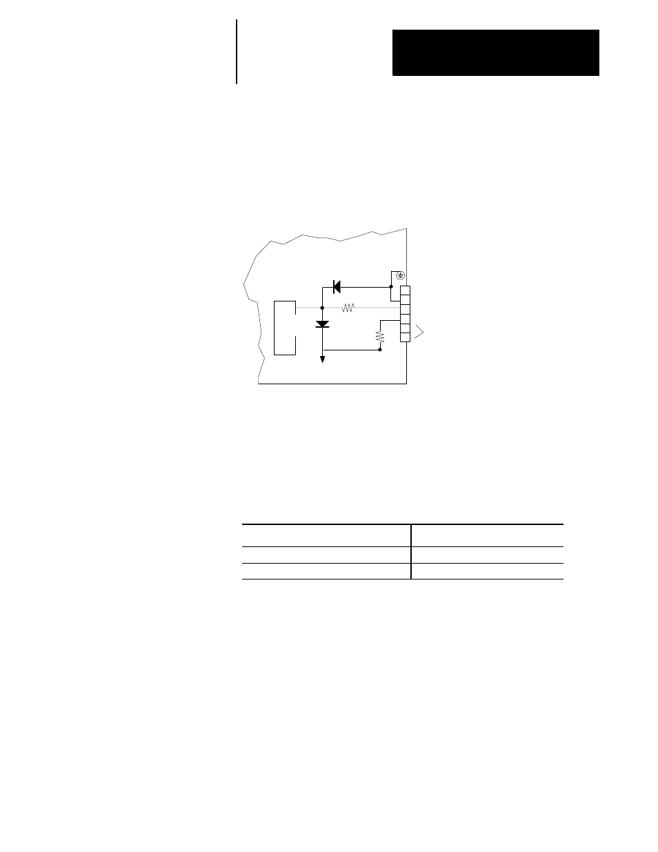
Figure 4B.39 shows the internal servo module circuitry that interfaces to
the touch probe connector. It is shown here to assist you in determining
whether your touch probe hardware is compatible.
Figure 4B.39
Internal Circuitry Supporting the Touch Probe
11309-I
5
4
3
2
1
Servo Module
26LS32
470 ohm
5V common
1000 ohm
+5 V dc
6
BAT/TP
TB1
NC
+5V Power
probe
GND
Shield
The following table indicates probing threshold voltages. Maximum Input
Threshold (critical if the control has been configured to fire on the falling
edge of the probe signal) indicates the voltage that the probe signal must
fall below to be considered as “fired”. Minimum Input Threshold (critical
if the control has been configured to fire on the rising edge of the probe
signal) indicates the voltage that the probe signal must rise above to be
considered as fired
Probe Thresholds
Voltage at Threshold
Minimum Input Threshold (probe circuit)
3.06 (min)
Maximum Input Threshold (probe circuit)
2.18V dc (max)
To avoid misfires use the threshold values from the above table to
determine the necessary signal voltage for steady state operation (probe not
fired). For probes configured to fire on the falling edge the steady state
voltage must remain above 3.06 volts. For probes configured to fire on the
rising edge the steady state voltage must remain below 2.18 volts.
Wiring a Probe for Rising Edge Configurations
Typical wiring of a simple contactor type touch probe configured to fire on
the rising edge of the probe signal, requires the addition of a 1000 ohm pull
down resistor. Figure 4B.40 shows a typical wiring diagram compatible
with most probe designs configured to trigger on the rising edge of the
probe’s signal.