5 rs-422 signal description – Rockwell Automation 8520 9/Series CNC Integration Maintenance Manual Documentation Set User Manual
Page 440
Section 8
Communication Interface
8-7
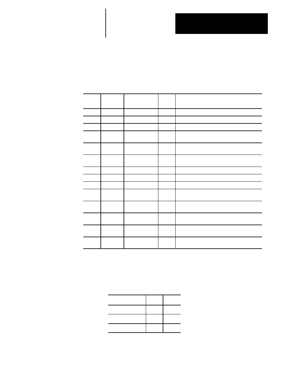
RS-422 sends and receives the signals in Table 8.C to and from the control.
The control is a data communication equipment (DCE) device.
Table 8.C
RS-422 Connector Pin Assignment
Pin No.
Signal
Code
Signal Name
Signal
Type
Description
1
SH
Shield
Shield
2
SD A
Send data A
Input
Data is sent from the peripheral to the control.
3
RD A
Receive data A
Output Data is transmitted from a control to a peripheral.
4
RS A
Request to send A
Input
The peripheral turns “ON”when requesting to send
data to the control.
5
CS A
Clear to send A
Output The control turns “ON”when the control is ready to
transmit or receive data.
6
DM A
Data set ready A
Output The peripheral turns “ON”when it is ready to trans-
mit or receive data.
7
SG
Signal Ground
Ground for each signal line.
8
TR A
Data term ready A
Input
Data is transmitted from a peripheral to the control.
9
SD B
Send Data B
Input
Data is sent from the peripheral to the control.
10
RD B
Receive data B
Output The peripheral turns “ON”when requesting to send
data to the control.
11
RS B
Request to send B
Input
The control turns “ON”when data transmission from
peripheral to the control is permitted.
12
CS B
Clear to send B
Output The control turns “ON”when the control is ready to
transmit or receive data.
13
DM B
Data set ready B
Output The peripheral turns “ON”when it is ready to trans-
mit or receive data.
14
TR B
Data terminal
ready B
Input
Data is transmitted from a peripheral to the control.
Table 8.D indicates the signal conditions corresponding to control signal
ON/OFF status.
Table 8.D
Control Signal Status
Signal Conditions
Mark
Space
Control Signal
OFF
ON
Logic
1
0
Signal Level
A < B
A > B
8.5
RS-422 Signal Description