Rockwell Automation 8520 9/Series CNC Integration Maintenance Manual Documentation Set User Manual
Page 159
1
2
11281-I
Section 4B
Connecting the 3-axis Servo Module
4B-13
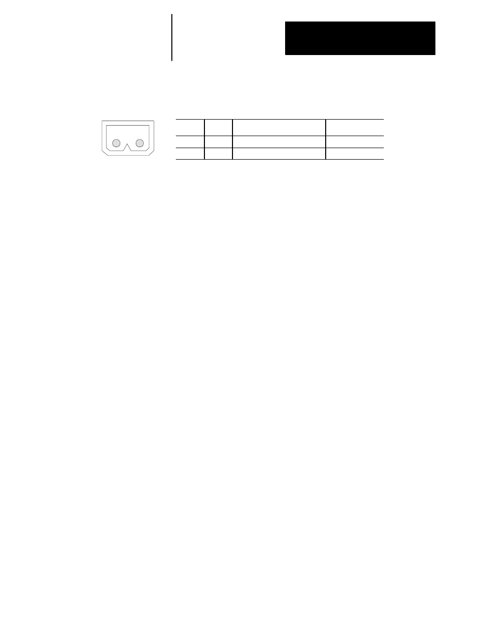
Figure 4B.11
Connector CN10 Pin Assignments
Pin No.
Signal
Description
Signal Destination
1
BAT_+
Battery Voltage Supply
Absolute Encoder
2
BAT_-
Battery Ground
Absolute Encoder
CN11 Optional Feedback Module Interface Connector
The servo module is interfaced with the optional feedback module through
connectors CN11 and CN12. Control signals from the servo module and
position feedback information from the non-motor mounted feedback
devices pass through this connector. Connector CN11 connects directly to
connector CN21M on the optional feedback module. A cable is not
required for this connection.
CN12 Optional Feedback Module Interface Connector
The servo module is interfaced with the optional feedback module through
connectors CN11 and CN12. Encoder feedback signals from the digital
servo module pass through this connector. Connector CN12 connects
directly to connector CN22M on the optional feedback module. A cable is
not required for this connection.
CN13 5V dc Encoder Power Connector
The digital servo module receives +5 V dc power directly from the main
power supply through connector CN13. This +5V dc power is used only
for powering the encoders. If the 5V dc encoder power is not used (i.e.
you are not using AB standard motors, you are using 15V dc encoders, or
some other power source is used), this connection is not needed.
Figure 4B.12 shows an end view of connector CN13 and lists the pin
assignments of this connector. For details on this connection refer to the
section in page 4D-4 that discusses connections to the Main Power Supply.
Important: This connector must be used to provide power for the
encoders if using the standard digital servo motors.