3a.6.1 wiring an incremental feedback device – Rockwell Automation 8520 9/Series CNC Integration Maintenance Manual Documentation Set User Manual
Page 104
Section 3A
Primary 9/230 Components
3A-21
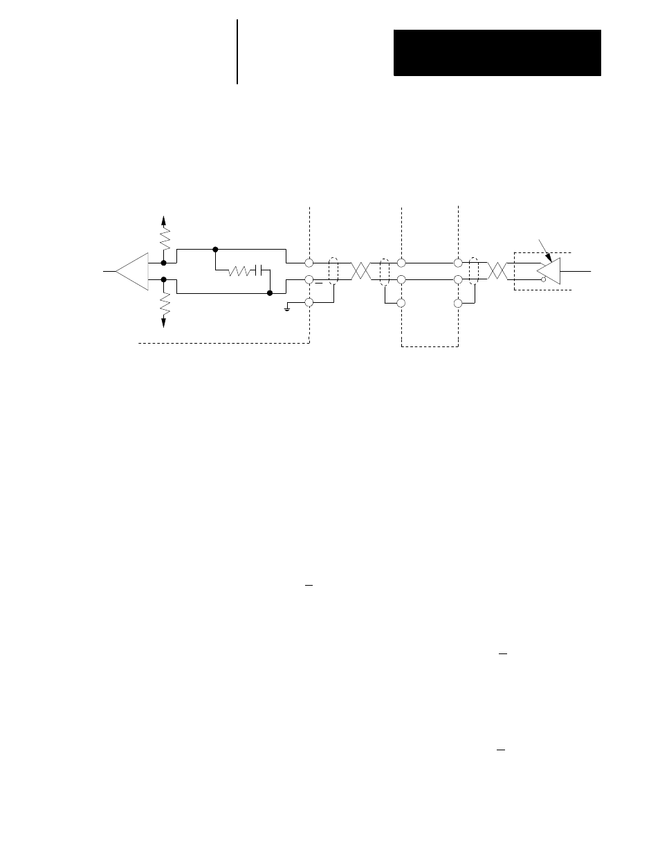
Figure 3A.13 shows an incremental feedback device equivalent circuit for
feedback channel A.
Figure 3A.13
Incremental Feedback Device Equivalent Circuit
Differential
Line Driver
Customer
Encoder
+5V
+5V
768
W
768
W
221
W
0.01u f
A
A
Ch A HI
Ch A LO
Termination Panel
+
--
Processor Module
8500-TPC
Cable
11306-I
Wiring Position Feedback
Feedback devices used with the control must be configurable such that the
marker Z is true at the same time that channels A & B are true. If you are
using an Allen-Bradley 845H encoder this requirement will already be met
if you wire them as shown in the cable diagrams on page 7A-1.
If you are using an encoder type feedback device other than the
Allen-Bradley 845H encoder, then use the following wiring procedure:
1.
Obtain the encoder output timing diagram from the vendor’s data
sheets. A typical one is provided in Figure 3A.14 as an example.
2.
On the timing diagram, look at the marker Z and its complement,
marker Z. Whichever one is low for most of the encoder revolution
and pulses high should be wired to “CH Z.HI” of the encoder
termination panel. Wire the remaining marker to “CH Z.LO” of the
encoder termination panel.
3.
Look at channel B and its complement, channel B. Whichever one is
high for at least part of the marker interval should be wired to
“CH B.HI” of the encoder termination panel. It is possible that both
channels meet this requirement depending on the encoder
manufacturer, in which case, use either one. Wire the remaining
channel to “CH B.LO” of the encoder termination panel.
4.
Look at channel A and its complement channel A and repeat as in
step 3 using “CH A.HI” and “CH A.LO” of the encoder termination
panel.
3A.6.1
Wiring an Incremental
Feedback Device