Touch probe connector - tb1, 5v dc encoder power connector - p3 – Rockwell Automation 8520 9/Series CNC Integration Maintenance Manual Documentation Set User Manual
Page 212
3
2
1
TO
UC
H
PR
O
BE
AN
AL
O
G
O
UT
J2
J3
J4
J1
1
3
2
4
FL
T
4
1
2
11282-I
Section 4C
Connecting the 4-axis Servo Module
4C-14
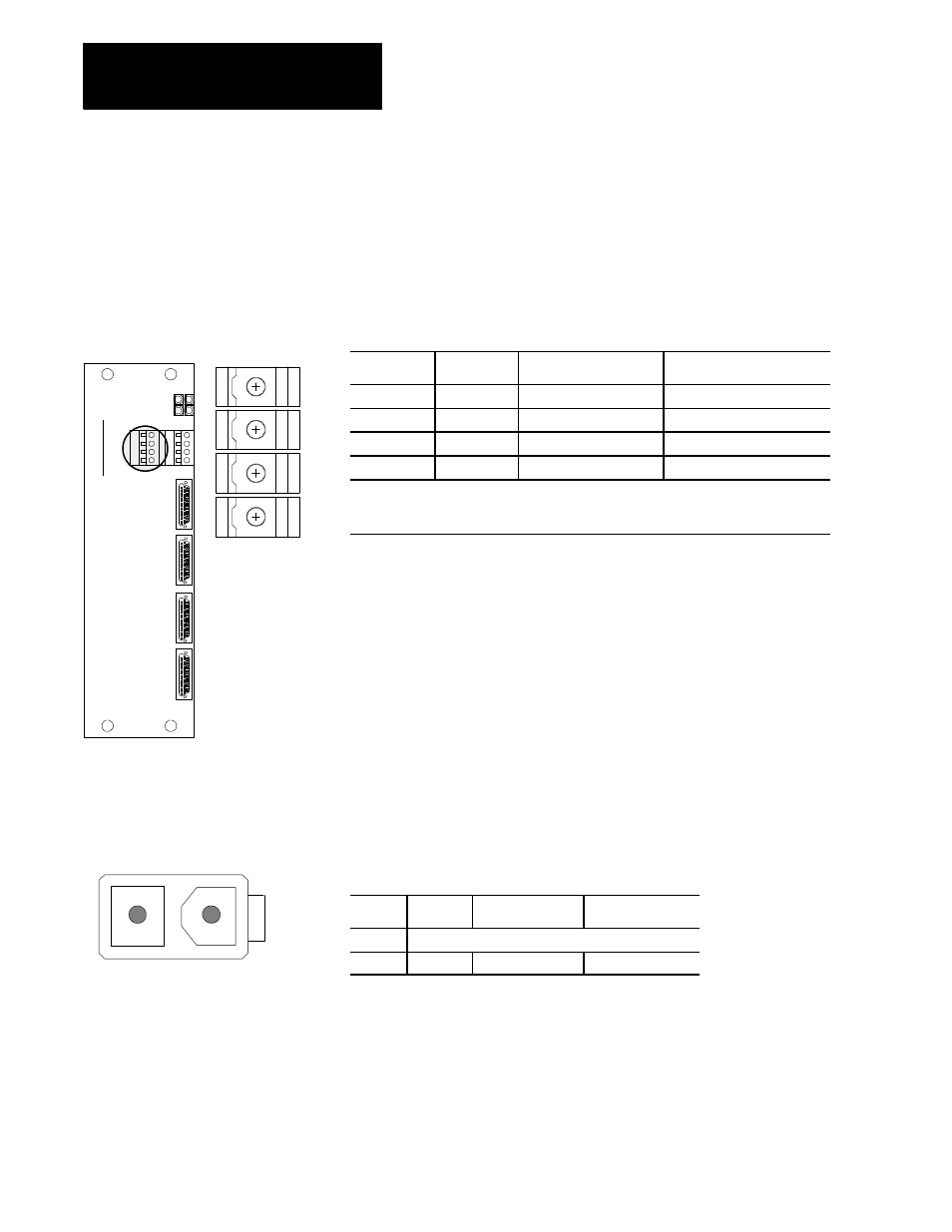
Touch Probe Connector - TB1
The servo module receives touch probe feedback through the connector
labeled TB1. Figure 4C.11 shows the location of this connector and lists
its terminal assignments.
Figure 4C.11
TB1 Connector , 4 Plug-type Terminal Block Connections.
Terminal No.
Signal
Description
Signal Destination
1
+5V
Probe Power
Touch Probe
2
PRB_FIRE
Probe Fired Signal
1
Servo Module
3
PE
Touch Probe Common
Touch Probe
4
Shield
Probe Shield
connect at module only
1
The True level (voltage transition the probe fires) is either “HIGH”or “LOW”as
defined by the AMP parameter PROBE TRANSITION. Refer to your AMP
reference manual for more information.
Important: The touch probe connector supports only +5V probing device
applications.
5V DC Encoder Power Connector - P3
The servo module receives +5V dc power directly from the main power
supply through connector P3. This +5V dc power is used only for
powering the encoder. If the EXT Power connection on the encoder
termination panel is used or if the 15V DC encoder power is used the
connection to P3 is not needed. Figure 4C.12 shows an end view of
connector P3 and lists the pin assignments. For details on this connection
refer to the section on the main power supply connections on page 4D-4.
Figure 4C.12
Connector P3, 2 pin male, Molex 5566-02A
Pin No.
Signal
Description
Signal Destination
1
Not Used
2
+ 5V dc
Encoder Power
Main Power Supply