Rockwell Automation 8520 9/Series CNC Integration Maintenance Manual Documentation Set User Manual
Page 548
I/O Interface
Section 10A
10A-25
The relay life of output contacts used in the E153 depends on the load
being controlled. The following shows contact performance for a load that
has surge suppression applied across it:
Load
Switching Voltage
Relay Life
Allen-Bradley Bulletin 500 Size 1
ac Contactor
120V ac
2,500,000 (operations)
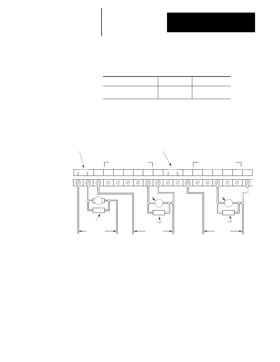
Figure 10A.19 showing the output device connection diagram, shows a
transistor output connection.
Figure 10A.19
Transistor Output Connection (E154)
B11
Relay type output
Relay type output
V dc1 A12
A13
A14
A15
A16
B12
B13
B14
B15
B16
A11
Noise
suppressor
Noise
suppressor
Noise
suppressor
COM
1
COM
2
M
Solenoid
Solenoid
Transistor output - Group 1
Transistor output - Group 2
115 V ac
24 V dc
48 V dc
L1 (H)
L2 (L)
dc (+)
dc (-)
dc (+)
dc (-)
Customer supplied
Customer supplied
Customer supplied
11324-I
V ac/V dc Common
V ac/V dc Common
V dc2
Important: Transistor output is a source type output, which is isolated by
means of a photocoupler. An external surge suppressor should be
connected to protect transistors from a transient voltage spike, which
occurs when an inductive device is turned off.
Important: A noise suppressor is not incorporated in the relay type output
circuits (terminals A11 and B11). Connection of an external surge
suppressor is recommended to protect the relay contact from a transient
voltage spike, which occurs when an inductive device is turned off.