Rockwell Automation 8520 9/Series CNC Integration Maintenance Manual Documentation Set User Manual
Page 805
Section 15B
Replacement Procedures
15B-49
To replace the push-button MTB panel I/O module:
1.
Disconnect the cable running from the operator panel power supply
or external power source to the power supply terminals.
ATTENTION: To guard against electrical shock hazards, never
make connections or disconnections at the AC distribution
network unless the main AC disconnect switch is open and
locked.
2.
Disconnect the fiber optic cables.
3.
Disconnect the input and output cables running from the push-button
MTB panel I/O module to the push-button MTB panel.
4.
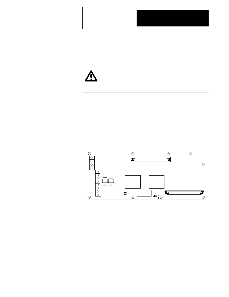
Remove the 9 mounting screws, shown in Figure 15B.13, that
connect the push-button MTB panel I/O module to the stand-offs.
Figure 15B.13
Push-Button MTB Panel I/O Module Mounting Screw Locations
+12V DC
GND
OP11
(out)
OP12
(in)
JPR1
JPR2
CN51
CN52
5.
Replace the old push-button MTB panel I/O module with a new
push-button MTB panel I/O module.
6.
Replace and tighten the 9 mounting screws then reconnect all cables.
7.
Set the node address to match the settings on the old push-button
MTB panel by cutting the wire jumpers on the new push-button MTB
panel I/O module.
8.
If you are using a custom MTB panel, set the shorting post of JPR3
over pins 2 and 3.
15B.32
Replacing the Push-Button
MTB Panel I/O Module