9a.2.5 flat panel horizontal adjustment – Rockwell Automation 8520 9/Series CNC Integration Maintenance Manual Documentation Set User Manual
Page 478
Section 9A
Operator Interface
9A-11
Set the node address by cutting the wire jumper(s) according to Table 9A.E
shown below.
Table 9A.E
Operator and Removable Operator Panel Node Address Setting
Node Address
Jumper
Hexidecimal
Binary
JP1
JP2
00
00
Short
Short
01
01
Open
Short
02
10
Short
Open
03
11
Open
Open
The node address may be any number between 00 and 03. You may have a
total of 4 interface assemblies on the I/O ring (if the removable operator
panel interface is used a separate power supply is required if you use more
than 2 assemblies). The same node address can be used for different types
of modules, but may not be used more than once for a specific type of
module.
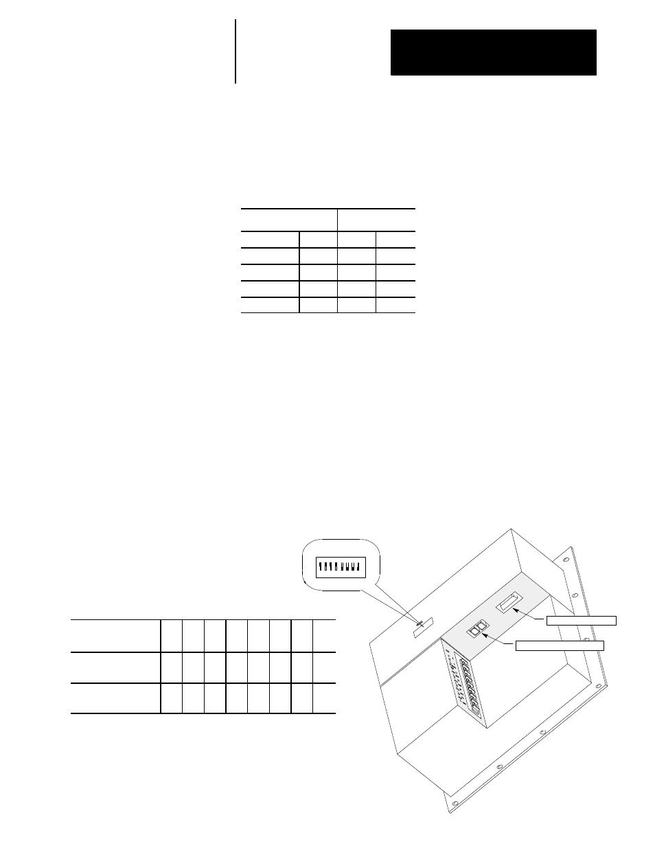
The flat screen operator panel has a set of dip switches used to adjust the
screens horizontal centering. Screen centering on the flat panel must be
adjusted for different connecting control types. Figure 9A.8 illustrates the
location and use of these dip switches.
Figure 9A.8
Flat Operator Panel Horizontal Adjustment Dip Switches
For this control type: Sw
1
Sw
2
SW
3
SW
4
SW
5
SW
6
SW
7
SW
8
9/230, 9/260, and
9/290 CNCs
On Off On Off Off Off Off Off
9/440 CNCs
(factory default)
On On On On Off Off Off Off
9A.2.5 Flat Panel Horizontal
Adjustment
Fiber Optic Connection
Video Connection
1
23
4
56
ON
7
8
HOR PHASE