Rockwell Automation 8520 9/Series CNC Integration Maintenance Manual Documentation Set User Manual
Page 307
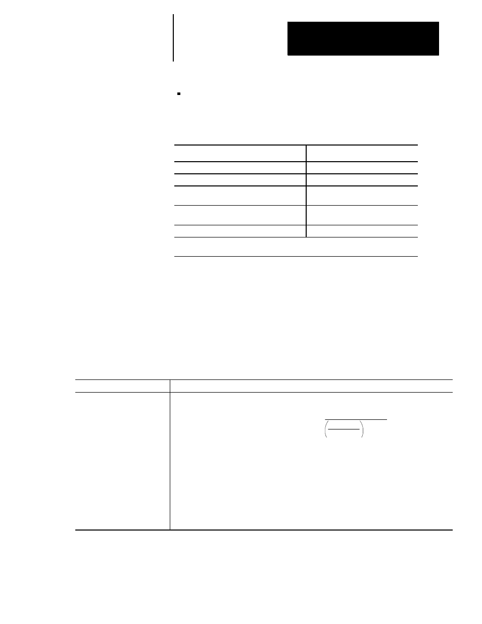
Maximum Encoder Channel Frequency =
Clock
360
x 1.15
90-Eq
Section 5B
9/440HR CNC/Drive System
5B-17
analog servo feedback -- If you are using one of the two analog ports to
control an axis these high--resolution feedback device ports can be used
for its position feedback.
The 9/440HR supports:
Feedback Device
Additional hardware
Allen-Bradley 845H Series Differential Encoders
----
Sony Magnascale Model GF-45E
Board-type detector model MD10-FR
Heidenhain Model 704
External interpolation and digitizing
model EXE602 D/5-F
Futaba Pulscale Model FM45NY
PCB interface Module model CZ0180
with cable PCB020EA
Heidenhain Distance--coded Marker
LS176
1
1
Refer to your vendor’s catalog for a complete listing of additional hardware you may need
to support distance--coded markers.
Other feedback devices can be compatible if they comply with the
specifications listed in Table 5B.A. Refer to the 9/Series CNC AMP
Reference Manual, publication 8520-6.4, for more information.
The following table lists feedback specifications for a differential encoder
however, this information can be interpreted to select an appropriate linear
scale.
Table 5B.A
Encoder Specifications
Item
Specification
Maximum Encoder Channel
Frequency (ECF)
Use the following equation to determine the maximum channel frequency
Where:
Clock -- is the Control’s Feedback Clock Frequency:
5 x 10
6
-- for 9/230, 9/440, and three--axis servo cards.
2.3 x 10
7
-- for 9/260 or 9/290 systems using a four--axis servo card
E
Q
= Quadrature Error in Degrees
1.15 = Our minimum recommended safety factor
As long as the actual feedback channel frequency does not exceed the maximum channel frequency
calculated above, the servo module should process the feedback data without a quadrature fault.