Rockwell Automation 8520 9/Series CNC Integration Maintenance Manual Documentation Set User Manual
Page 569
I/O Interface
Section 10A
10A-46
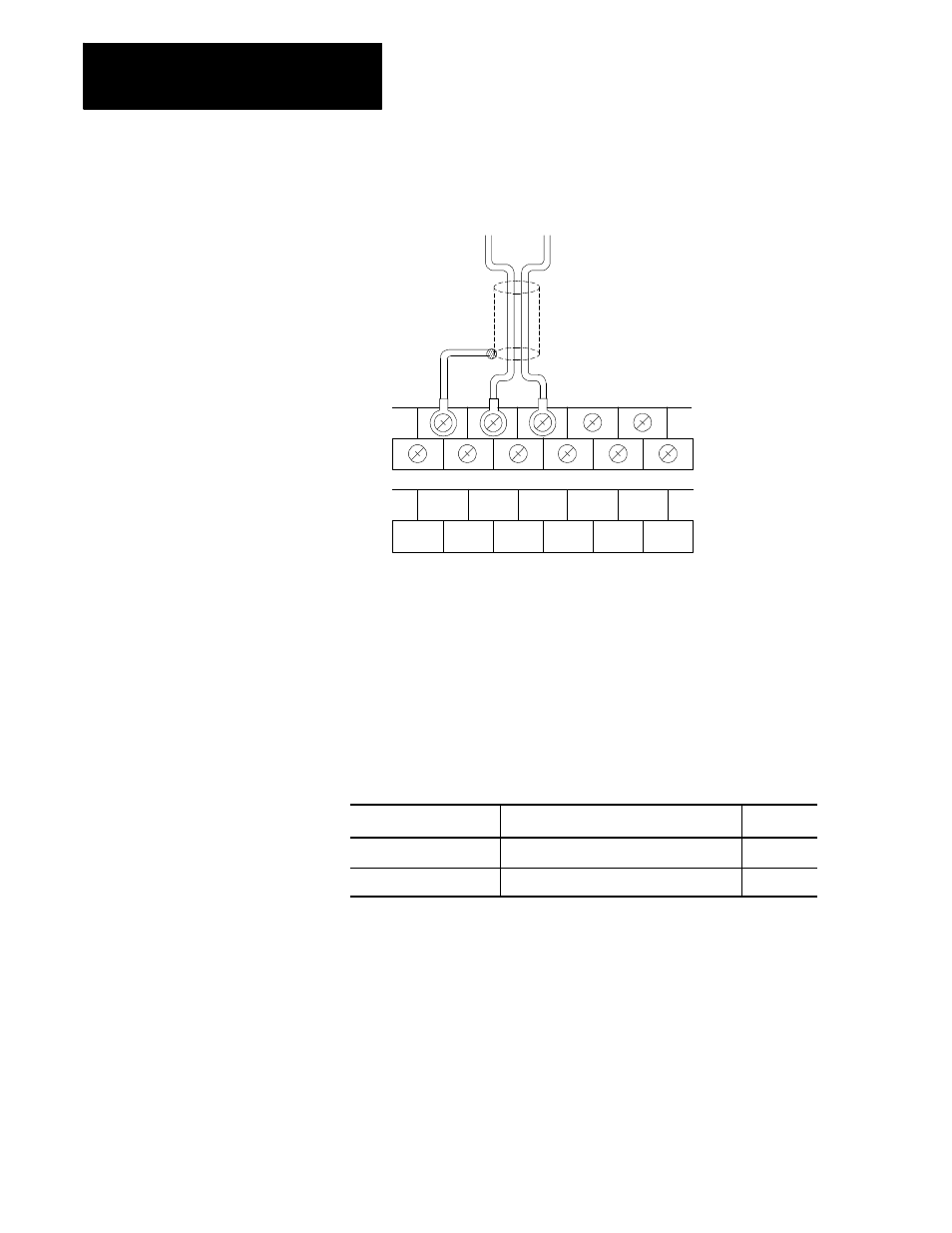
Figure 10A.36
E- Series Analog I/O Output Device Connection
CHASSIS
GND
COM
OUTPUT
CHASSIS
GND
NOT
USED
NOT
USED
NOT
USED
NOT
USED
CHASSIS
GND
CHASSIS
GND
CHASSIS
GND
Terminal
Block
Label
Shielded cable
To analog device
11341-I
Table 10A.AH lists the analog I/O connectors used to make the fiber optic
connections to the I/O ring. Each module connected to the system I/O ring
has an optical transmitter and receiver. Fiber optic cables connect
transmitters to receivers to form the I/O ring. Refer to Appendix A for
additional information on fiber optic cables and connectors.
Table 10A.AH
E- Series Analog I/O Fiber Optic Connectors
Connector on Digital I/O
Connected To
Remark
OP25 (RED)
Receiver on next module in I/O ring
Output
OP26 (BLacK)
Transmitter on previous module in I/O ring
Input
Different types of I/O devices can have the same node address, but devices
of the same type must each have a unique node address. Each analog I/O
is assigned a unique node address in the I/O assignment file of ODS. This
address corresponds to a switch setting on the analog I/O device.
Figure 10A.37 shows the location of the node address switch assembly on
the analog I/O.
10A.5.3
E- Series Analog I/O Fiber
Optic Connection
10A.5.4
E- Series Analog I/O Node
Address Setting