Rockwell Automation 8520 9/Series CNC Integration Maintenance Manual Documentation Set User Manual
Page 408
Section 7A
Connecting Components
7A-60
Table 7A.A
Cable and Connector List (continued)
Cable No.
Control
From Module and Connector
Cable Name
To Module and Connector
Cat. No.
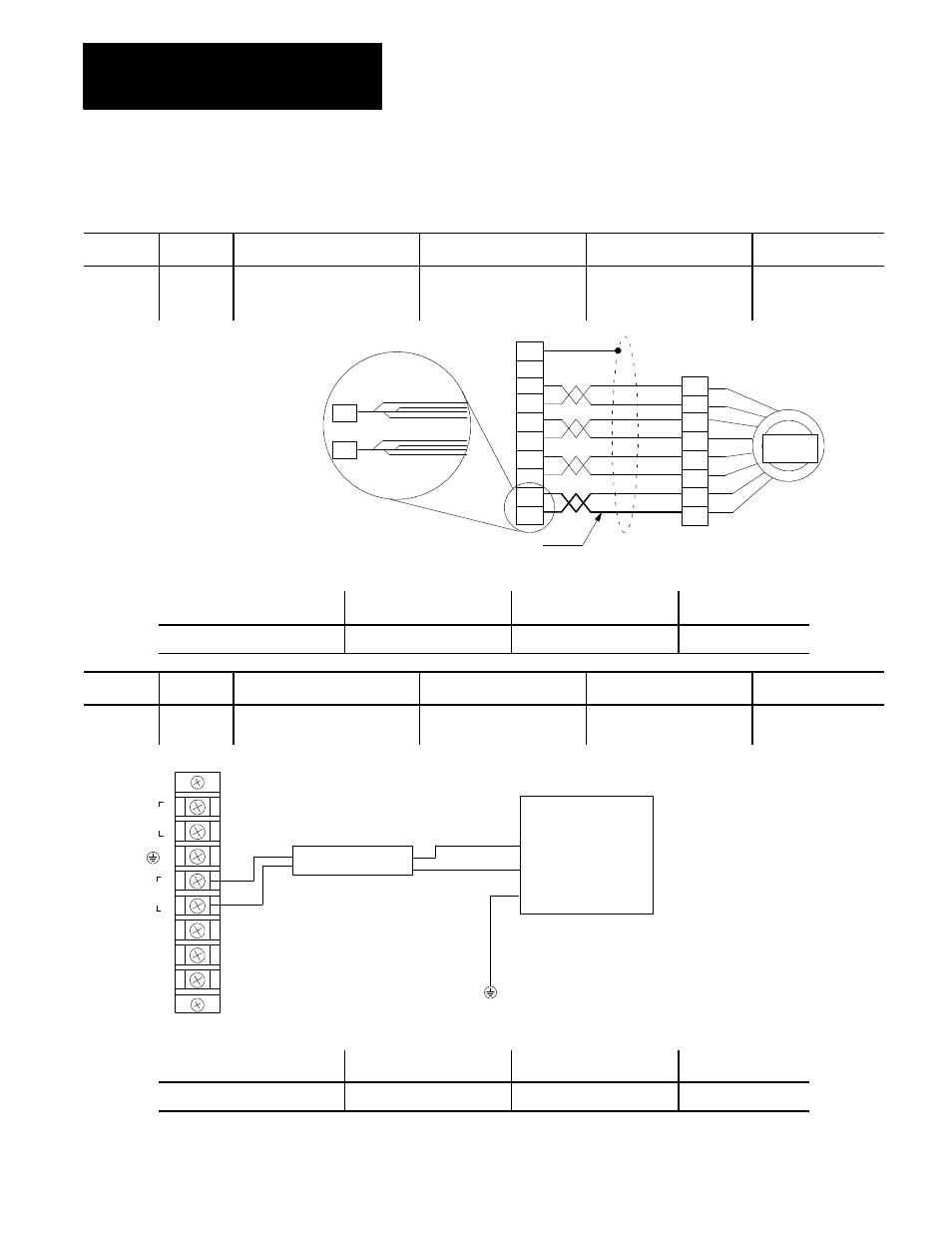
C52
9/440
Resolver--
based
9/440 Resolver--based System
Module Feedback Board
Encoder Signal Cable
AB 845H Encoder
Customer Supplied
16 AWG for encoder power
pins 6 and 12 (use four 22 gauge)
12
6
Use four 22 gauge twisted pair to make the
power connections to pins 6 and 12. Strip 1 inch
of one lead and solder into pin. Solder the three
remaining leads to the exposed one inch of wire
to make the equivalent of 16 gauge wire. Use
the appropriate wire tape. Repeat for both pins.
A
H
I
B
C
J
AB 845H
Encoder
1
7
8
3
9
5
11
12
D
F
6
2
Connector On End of Cable
Cable Type
Connector On End of Cable
Max. Cable Length
AMP 770581--1
Belden 8307
MS Type
25 m (82 ft.)
Cable No.
Control
From Module and Connector
Cable Name
To Module and Connector
Cat. No.
C53
9/440 (all)
On/Off Power Control Module
115V Transformer Feed
24V Logic Transformer
(customer supplied)
Prepared by Customer
To local cabinet
PE bus
L1
ac
IN
L2
PE
L1
L2
COMMON
AUX
ac
On/Off Power Control Module
ON SW
OFF SW
High
Low
Customer supplied
24V logic transformer
Important: Make sure 24V logic power is applied
before allowing 3--phase power to come up. Logic
power must be applied to the system module first.
C53
Connector On End of Cable
Cable Type
Connector On End of Cable
Max. Cable Length
Miscellaneous
Belden 9409
Miscellaneous
Line Drop Limitation