Rockwell Automation 8520 9/Series CNC Integration Maintenance Manual Documentation Set User Manual
Page 192
Section 4B
Connecting the 3-axis Servo Module
4B-46
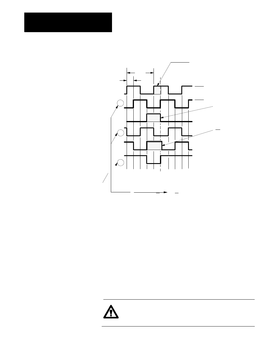
Figure 4B.37
Example of a Typical Vendor Encoder Timing Diagram
1 cycle
Hi
Lo
Channel A
B
A’
B’
Z’
Z
Optional
STEP 3
C h a n n e l A is h ig h a t
le a s t p a rt o f m a r k e r
in te r v a l. C o n n e c t
o
t
“C H A . H I” o f
te rm in a tio n p a n e l.
STEP 1
H ig h m a rk e r
in te rv a l. C o n n e c t to
“C H Z . H I” o f
te rm in a tio n p a n e l.
STEP 2
B is h ig h fo r a t
le a s t p a r t o f m a r k e r
in te r v a l. C o n n e c t t o
“C H B . H I” o f
te r m in a tio n p a n e l.
CCW rotation
viewing shaft
W ire C H B , C H A , a n d C H Z to C H B L O ,
C H A L O a n d C H Z L O , re s p e c tiv e ly ,
o n th e te rm in a tio n p a n e l.
Be l o w w ir in g is a n e x a m p le o n ly o f
a ty p ic a l v e n d o rs e n c o d e r . S e e y o u r e n c o d e r
v e n d or s tim in g d ia g r a m .
N O T E :
11307-I
90°
,
2.
On the timing diagram, look at the marker Z and its complement,
marker Z’. Whichever one is low for most of the encoder revolution
and pulses high should be wired to “CH Z.HI” of the encoder
termination panel. Wire the remaining marker to “CH Z.LO” of the
encoder termination panel.
3.
Look at channel B and its complement, channel B’. Whichever one is
high for at least part of the marker interval should be wired to
“CH B.HI” of the encoder termination panel. It is possible that both
channels meet this requirement depending on the encoder
manufacturer, in which case, use either one. Wire the remaining
channel to “CH B.LO” of the encoder termination panel.
4.
Look at channel A and its complement channel A’and repeat as in step
3 using “CH A.HI” and “CH A.LO” of the encoder termination panel .
ATTENTION: You can find a marker even if your encoder is
not phased properly. An improperly phased encoder will still
home successfully.