Figure 9a.16 push-button mtb panel, 9a-27 – Rockwell Automation 8520 9/Series CNC Integration Maintenance Manual Documentation Set User Manual
Page 494
Section 9A
Operator Interface
9A-27
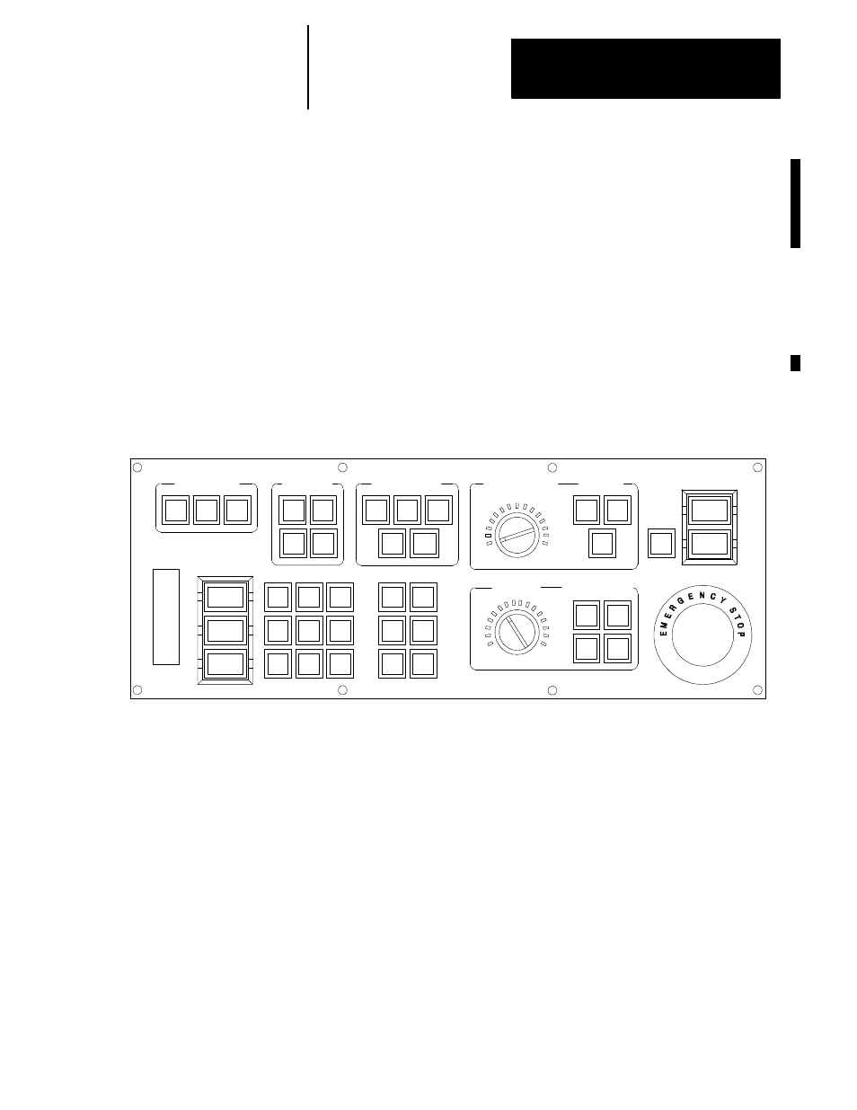
The push-button MTB panels are used to provide the user with manual
control over various system functions. These system functions are
selected using the various switches and push buttons on the push-button
MTB panel. The selected functions are then interfaced to the control via a
fiber optic I/O module.
Important: A PAL module that provides the PAL logic necessary to
decode the push-button MTB panel functions is available on Motion
Control Bulletin Board. Refer to the 9/Series CNC PAL Reference
Manual, publication 8520-4.3, for more information.
Figure 9A.16 shows a front view of all of the push-button MTB panels.
Figure 9A.16
Push-Button MTB panel
19930
JOG SELECT
SPINDLE SPEED
OVERRIDE
SPINDLE
MODE SELECT
SPEED/MULTIPLY
RAPID FEEDRATE
OVERRIDE
0
50
100
AUTO
MDI
MAN
INCR
CONT
HAND
HOME
CYCLE
START
SINGLE
BLOCK
CYCLE
STOP
+X
+4
--X
+Y
TRVRS
--Y
+Z
--4
--Z
F1
F2
F3
F4
F5
F6
CCW
CW
OFF
F1
25
50
100
LOW
X1
MEDL
X10
MED
X100
MEDH
X1000
HIGH
X10000
%
ESTOP
RESET
OFF
ON
AXIS
FUNCTION
FEEDRATE
OVERRIDE
50
120
150
Only the three push-button MTB panels are covered in these sections. The
system installer may develop custom MTB panels for specific applications.
Refer to the system installer’s literature for any information on custom
MTB panels.
If a custom MTB panel is to be used, the MTB I/O module can be
purchased separately to interface a custom MTB panel with the system I/O
ring. To use a custom panel with the I/O module, you must set JPR3 to the
Custom Panel position.