Wiring a probe for falling edge configuration, Wiring a probe to multiple servo cards – Rockwell Automation 8520 9/Series CNC Integration Maintenance Manual Documentation Set User Manual
Page 228
Section 4C
Connecting the 4-axis Servo Module
4C-30
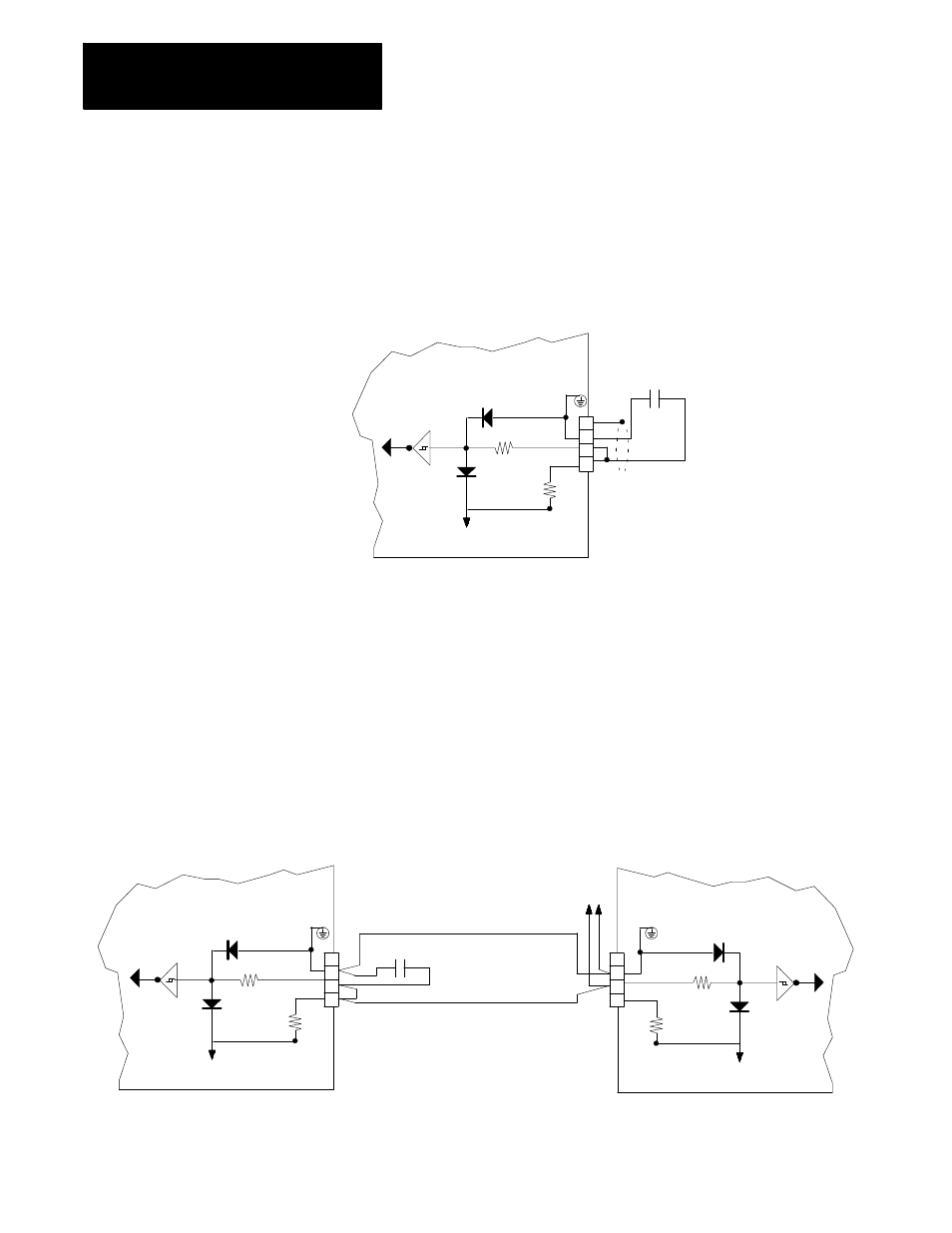
Wiring a Probe for Falling Edge Configuration
Figure 4C.21 shows a typical wiring diagram compatible with most probe
designs configured to trigger on the falling edge of the probe signal.
Figure 4C.21
Typical Wiring of a Touch Probe Configured for Falling Edge Trigger
11309-I
3
2
1
Servo Module
470 ohm
5V common
1000 ohm
+5 V dc
4
Probe Contact
to encoder interface
Wiring a Probe to Multiple Servo Cards
Systems with more than one servo module should have their touch probe
connections tied together in parallel. This allows the position to be latched
on all servo modules at the same time with the same input. Only one
power connection needs to be made (with pull up or down resistor). The
other probe connections should be made in parallel on all servo cards.
Figure 4C.22 shows a typical wiring diagram for multiple servo cards.
Figure 4C.22
Multiple Servo Card Touch Probe Wiring ( Falling Edge Trigger)
Servo Module 1
470 ohm
5V common
1000 ohm
+5 V dc
Probe Contact
Electrically tie Terminal 5 to 5
and Terminal 4 to 4 of all servo modules
in the same 9/Series enclosure that use
the same touch probe.
Servo Module 2
470 ohm
5V common
1000 ohm
+5 V dc
To Additional
Servo Modules
4
3
2
1
to encoder interface
to encoder interface
4
3
2
1