Input interface ribbon cable – Rockwell Automation 8520 9/Series CNC Integration Maintenance Manual Documentation Set User Manual
Page 531
I/O Interface
Section 10A
10A-8
The push-button MTB panel I/O module is included with the push-button
MTB panel. It can also be purchased separately to interface a custom
MTB panel to the control. This module provides 44 inputs and 18 outputs
to the I/O ring.
The push-button MTB panel I/O module is interfaced with the system I/O
ring through fiber optic cables, which are connected to the optical receiver
and transmitter on this module. Refer to Appendix A for additional
information on fiber optic cables and connectors.
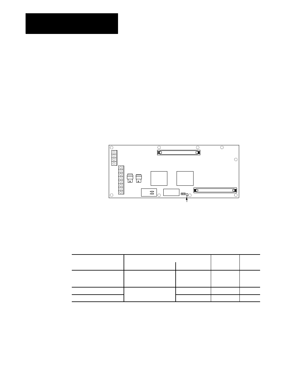
Figure 10A.5 shows the external appearance of the push-button MTB panel
I/O module.
Figure 10A.5
Push-Button MTB Panel I/O Module External Appearance
+12V dc
GND
OP11
(out)
OP12
(in)
CN51
CN52
I/O ring fault indicator
JPR1
JPR2
Table 10A.C lists the connectors used to connect the push-button MTB
panel I/O module to the operator panel power supply and a custom MTB
panel.
Table 10A.C
Push-Button MTB Panel I/O Module Connectors
Connector On
Connected To
Cable
Remark
MTB I/O Module
Module
Connector
Number
+12V
GND
Operator Panel Power Supply
(or External Power Supply)
+12V
BT03
GND
C28
CN51M
Custom MTB Panel
Input
CN52M
Output
Input Interface Ribbon Cable
MTB panel data is sent to the push-button MTB panel I/O module via the
input interface ribbon cable. It is then sent to the control via the fiber optic
I/O ring. Table 10A.D lists the pin assignments for the input interface
ribbon cable for a custom MTB panel. If you are using an Allen-Bradley
MTB panel refer to page 9A-30 for the pinouts of this cable.
10A.2
Push-Button MTB Panel I/O
Module
10A.2.1
Push-Button MTB Panel I/O
Module Pin Assignments