Rockwell Automation 8520 9/Series CNC Integration Maintenance Manual Documentation Set User Manual
Page 105
Section 3A
Primary 9/230 Components
3A-22
If the previous procedure is not performed correctly, inconsistent homing
of the axis may occur. If your encoder phasing cannot provide an interval
at which the marker and both channels are simultaneously true, the encoder
should be considered incompatible with the control.
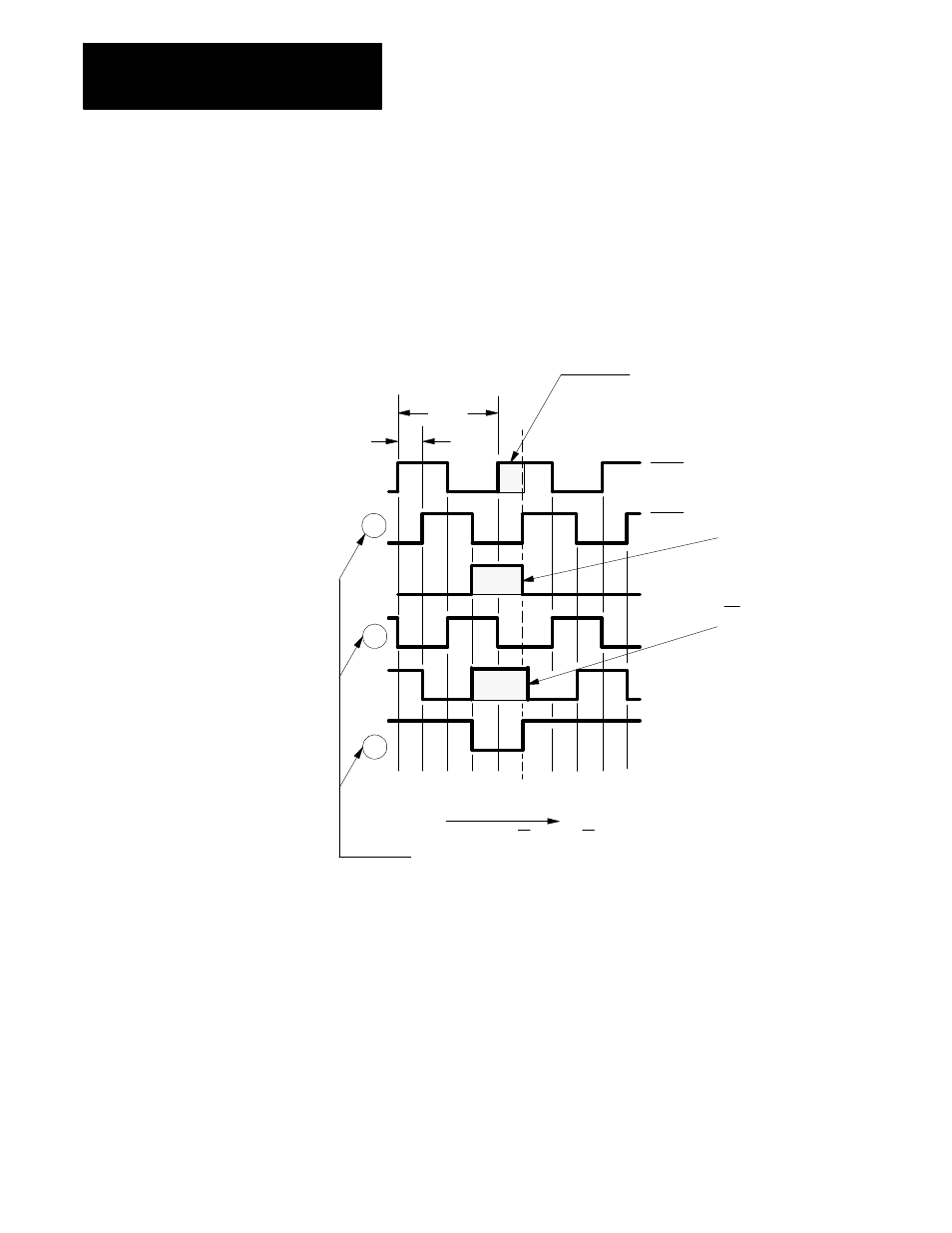
Figure 3A.14
Example of a Typical Vendor Encoder Timing Diagram
1 cycle
Hi
Lo
Channel A
B
A’
B’
Z’
Z
Optional
STEP 3
C h an ne l A is h igh at
le a st pa rt o f m a rker
in terval. C o nn ect o
t
”C H A . H I” of
te rm ina tio n p a ne l.
STEP 1
H ig h m a rker
in terva l. C onne ct to
”C H Z. H I” of
te rm inatio n pane l.
STEP 2
B is h ig h fo r a t
le a st p a rt o f m a rk e r
in te rv a l. C o n n e c t to
”C H B . H I” o f
te rm in a tio n p a n e l.
CCW rotation
viewing shaft
W ire CH B, CH A , and CH Z to CH B LO ,
CH A LO and CH Z LO , respectively,
on the term ination panel.
Below w irin g is an e xa m p le o n ly o f
a typ ica l ve n d ors e n co de r. S e e you r e n co de r
ve nd or s tim in g d ia g ra m .
NOTE:
11307-I
90
°
,
Important: Since positive and negative axis directions can be assigned
without regard to encoder rotation directions, it is possible for the feedback
direction to be ”backwards”. This is easily corrected before attempting to
command axis motion through the AMP parameter Sign of Position
Feedback. Refer to the 9/Series CNC 9/230, 9/260, and 9/290 AMP
Reference Manual, publication 8520-6.4, for more information.