Rockwell Automation 8520 9/Series CNC Integration Maintenance Manual Documentation Set User Manual
Page 567
I/O Interface
Section 10A
10A-44
Table 10A.AF lists the input specifications for the analog I/O.
Table 10A.AF
E- Series Analog I/O Input Specifications
Item
Specifications
Remark
Number of Input Points
1
Input Voltage Range
Bipolar: -10 to +10 V dc
Unipolar: 0 to +10V dc
Range selected by switch next to the
node address switch on the analog I/O
Resolution
12 bit binary
Input Impedance
More than 100 Kohms
-10V to +10V
Conversion Rate
Interval: Less than 100
m
sec
Time: Less than 30
m
sec
Approx. 64
m
sec
Approx. 20
m
sec
Maximum Input Voltage
±
25 V dc
Common Mode Rejection
More than 70dB
From dc to 60 Hz
Connection
Terminal Block
PAL Variable Values
Bipolar:
0 -- 2047 (0 to +10V dc)
2048 -- 4096 (--10 to 0 V dc)
Unipolar:
0 -- 4096 (0 to +10V dc)
The PAL variable name is determined in
your I/O configuration using ODS.
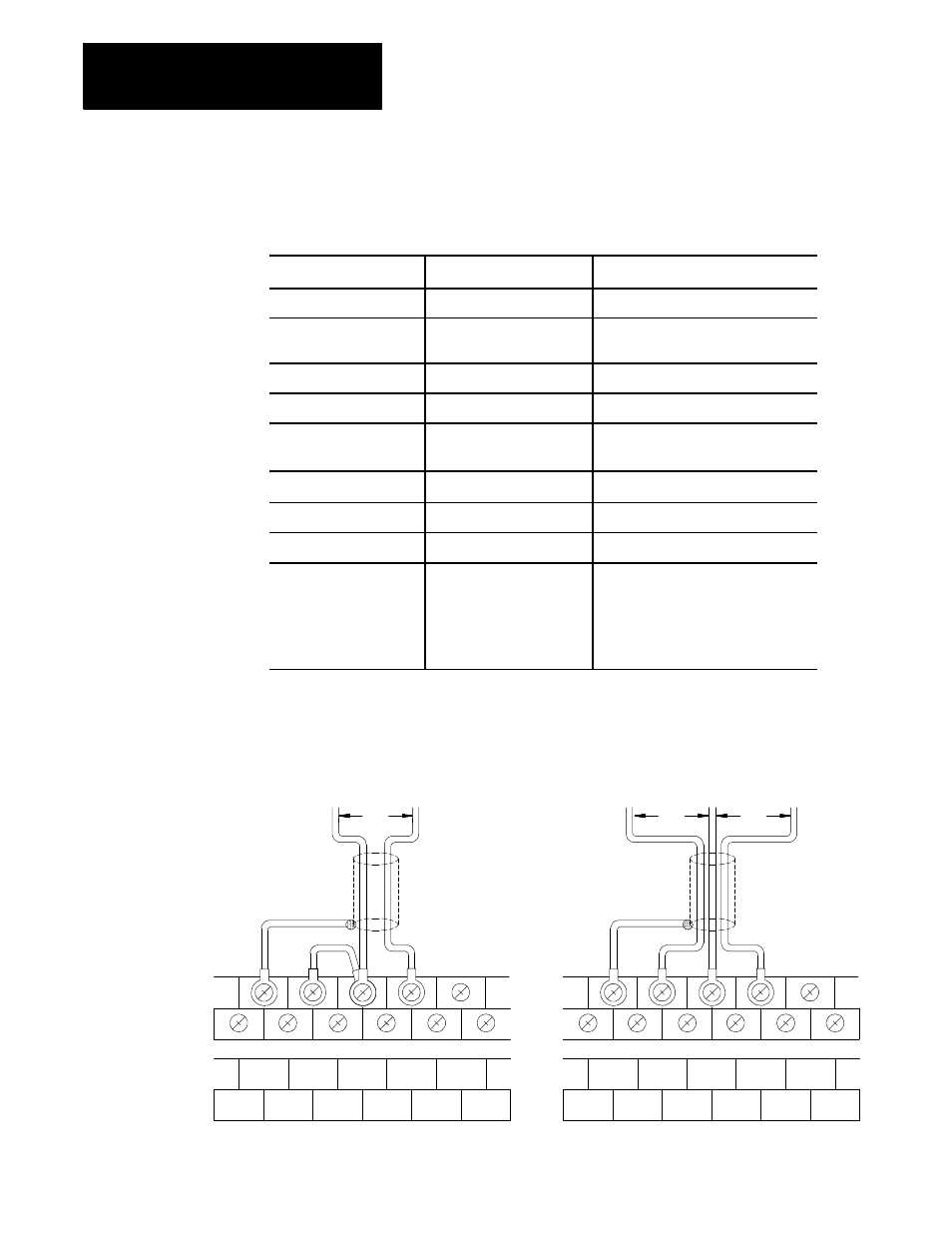
Figure 10A.35 shows a typical analog I/O input device connection.
Figure 10A.35
E- Series Analog I/O Input Device Connection
Single
Input
Differential
Input
Terminal
Block
Label
Shielded cable
Shielded cable
CHASSIS
GND
INPUT
( - )
COM
INPUT
( + )
CHASSIS
GND
CHASSIS
GND
CHASSIS
GND
CHASSIS
GND
CHASSIS
GND
NOT
USED
NOT
USED
CHASSIS
GND
INPUT
( - )
COM
INPUT
( + )
CHASSIS
GND
CHASSIS
GND
CHASSIS
GND
CHASSIS
GND
CHASSIS
GND
NOT
USED
NOT
USED
From analog device
e
e
2
e
1
e=e
1
-e
2
From analog device
11340-I