13a.9 feedback devices – Rockwell Automation 8520 9/Series CNC Integration Maintenance Manual Documentation Set User Manual
Page 662
B
A
C
D
E
F
G
H
I
Section 13A
Connecting 8520 Digital Drive Systems
13A-28
Figure 13A.3 lists the pin assignments for the A series 8500 digital servo
motor connector with brake.
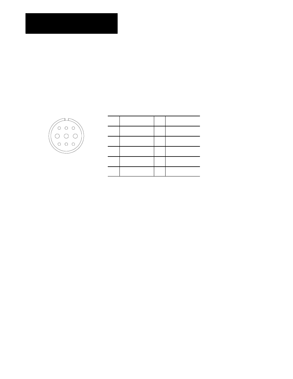
Figure 13A.4 shows the pin layout and pin assignments for the B series
8500 digital servo motor connector with brake.
Figure 13A.4
B Series 8500 Digital Servo Motor Connector and Pin Assignments (with
brake)
Pin
Signal
Pin
Signal
A
Thermal Protector
F
Phase C (W)
B
Thermal Protector
G
Ground and Shield
C
--
H
Brake Terminal
D
Phase A (U)
I
Brake Terminal
E
Phase B (V)
Each servo motor is equipped with a feedback device that is mounted on
the end of the motor that is opposite the shaft end. This feedback device
can be either an absolute or an incremental encoder. The servo module
supplies these encoders with their required +5V power supply.
Each servo motor may also be equipped with a second feedback device for
greater accuracy for positioning feedback. This second feedback device is
normally mounted directly to the moving axis member to avoid
inaccuracies caused by the motor gearing and drive components. When a
second feedback device is used the motor mounted encoder must remain
and is used for velocity feedback as well as motor commutation.
The spindle motor can also be equipped with a feedback device. This
feedback device must be an incremental encoder with A quad B format.
The servo module can supply the spindle encoder with +5V or +15V
power.
13A.9
Feedback Devices