Rockwell Automation 8520 9/Series CNC Integration Maintenance Manual Documentation Set User Manual
Page 625
Section 12
Wiring A-B Analog Drives
12-3
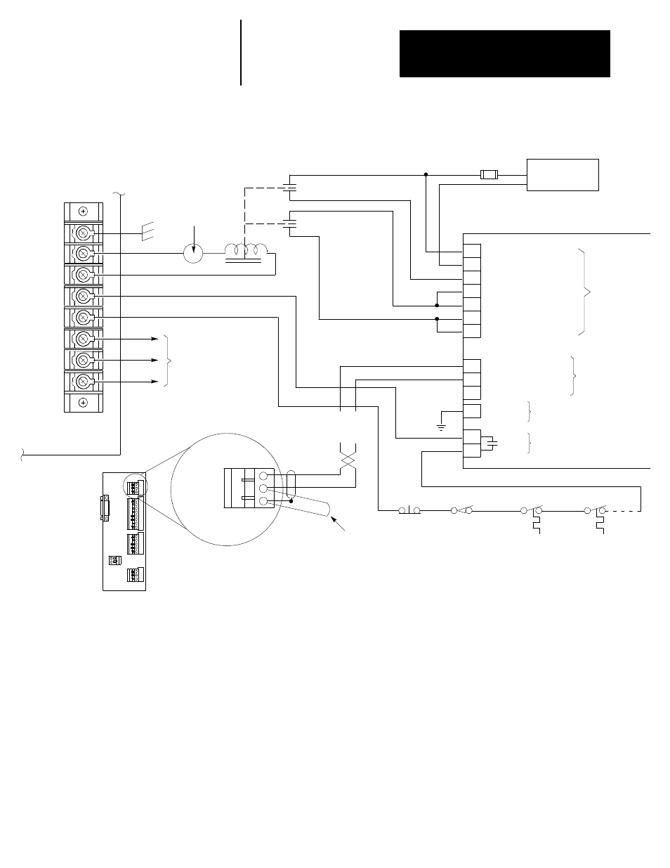
Figure 12.2
Wiring Diagram For Series 1387B Drives
21
23
25
27
34
37
39
1
3
5
48
50
8
DRIVE
DRIVE
DR RET
SHLD
1771 HTE
Encoder
Termination
Panel
7
6
5
4
Reset 3
Common 2
E-STOP 1
Motherboard (9260 and
9/290) or Processor Board
(9/230) terminal block BT1
Connection to MTB
Panel E-STOP
and E-STOP Reset
E-STOP
status
relay
Status
relay
power
User Power to
drive logic
115V ac
1387B Servo Amplifier (see note 1)
Control Power High
Control Power Low
Coast/DB Stop
Internal tie Point
High Accel/decel Rate
Internal Logic Power
Enable Input
TB2
Run Reference (+)
Run Reference (--)
Shield
Common
TB5
TB1
Fault
TB5
Velocity Command
Remote
E-STOP
Axis
Overtravel
Motor
Thermal
Overload
Drive
XFMR
Thermal
Overload
NOTE:
1. The control works only with 1387 drives
that use 115V ac and have the dynamic
braking option. Refer to Bulletin 1387 User
Manual (Publication 1387-5.0) for power
wiring and motor connection.
2. We recommend installation of this connection. Remove it if
excessive noise from chassis ground occurs.
3. The connection from the termination panel to the drive should
be as short as possible. We recommend less than 20 ft.
See
note
3
See
note 2
If your control has terminal 8,
then connect it to chassis ground.
If terminal 8 is not present on
your control, then this type of
grounding is not necessary.
8