Rockwell Automation 8520 9/Series CNC Integration Maintenance Manual Documentation Set User Manual
Page 377
Section 7A
Connecting Components
7A-29
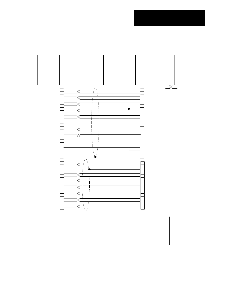
Table 7A.A
Cable and Connector List (continued)
Cable No.
Control
From Module and Connector
Cable Name
To Module and Connector
Cat. No.
C14
9/230, 9/260,
9/290
8520 Digital
9/230 Processor (8520-DSP only)
servo connectors (J1,J2, or J3) or
4-axis Digital Servo Module
(8520-ENC4) Servo Connector
(J1, J2, J3, or J4)
Drive and Abs. Encoder
Signal Cable
8500 Servo Motor Encoder
and 8520 Digital Servo
Amplifier CNA1-CNA3
Prepared by Customer
Indicates
twisted
pair
With 5V dc
absolute
encoders
Shield wires, no
connection at control end
for either shield wire.
13
43
8
38
35
5
36
6
37
7
14
44
12
42
1
2
3
6
7
10
11
12
13
14
15
17
18
22
23
Absolute
Encoder
Connection
1
Drive Connection
2
44- pin D-shell
A
B
C
D
E
F
G
H
R
11
41
10
40
39
9
15
16
19
28
29
31
20
21
22
24
25
26
34
J
T
23
S
gnd
chb_lo
gnd
gnd
gnd
chz_lo
chb_hi
chz_hi
gnd
/enable
+5v_enc
+5v_enc
+5v_enc
not used
+5v_enc
+5v_enc
not used
not used
enable
pwm_v_hi
ext_bat
/status
status
/pwm_u_lo
pwm_u_hi
chu_lo
pwm_w_hi
/pwm_w_lo
/pwm_v_lo
+5v_enc
cha_lo
cha_hi
not used
encoder reset pin
b channel output
frame ground
z channel output
+v (battery)
0v (battery)
a channel output
/z channel output
/b channel output
/a channel output
5v (power supply)
0v
I
/I
I
/I
1
a
b
a
b
1
2
2
/enable
shield
pwm_a
l
l
/pwm_c
/l
enable
pwm_c
/l
/pwm_a
pwm_b
/pwm_b
/status
status
a
a
b
b
Connector On End of Cable
Cable Type
Connector On End of Cable
Max. Cable Length
44--pin Miniature D-shell (has pins)
8520-MD44M
Belden 8312 (encoder cable)
Belden 9833 (drive signal cable)
MS Style E20-29S
8520-C17F to encoder
1
Honda MR-25LF (has
sockets) 8520-H25F to drive
2
25m (82 ft)
1
The Z channel output is used for the marker signal.
2
These cables are 22 AWG twisted pairs. Multiple lines (4) must be used to provide the equivalent of 16 AWG encoder power leads.