Rockwell Automation 8520 9/Series CNC Integration Maintenance Manual Documentation Set User Manual
Page 488
Section 9A
Operator Interface
9A-21
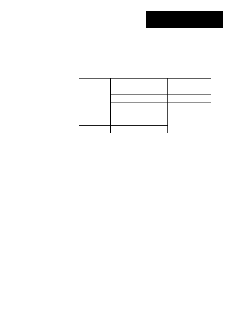
Table 9A.I shows the output specifications of the removable operator panel
interface power supply. For input specifications and fuse specifications
refer to page 4D-5.
Table 9A.I
Interface Assembly Power Supply Output Specifications
Item
Specifications
Remark
Outputs
5 V dc (3 terminals) 0.4 A/channel
For HPGs
12 V dc (1 terminal) 1.5 A
For MTB Panel I/O Module
5 V dc
For Keyboard I/O Module
12 V dc
For Monochrome CRT
Protection Function
Overcurrent protection
Connection
Terminal Block
Your removable operator panel connects to the 9/Series control through the
removable operator panel interface assembly you installed as discussed on
page 9A-15. The connection between removable operator panel and
interface assembly is made via a 10 ft (max length) cable. This cable is
provided with your removable operator panel.
Attach the removable operator panel cable between the interface assembly
connector CN5 and the 37--pin D--shell connector on the front of your
removable operator panel. You can attach or detach the operator panel at
any time. We do not recommend, however, disconnecting this panel while
in the middle of editing online or Patch AMP or while editing a part
program.
9A.3.2
Connecting/Disconnecting
the Removable Operator
Panel