Rockwell Automation 8520 9/Series CNC Integration Maintenance Manual Documentation Set User Manual
Page 166
1
2
3
4
11864-I
Section 4B
Connecting the 3-axis Servo Module
4B-20
CN23M External +15V dc Power Supply Connector
Use connector CN23M on the optional feedback module to connect an
external +15V dc power supply to the optional feedback module.
Typically the optional feedback module receives +15V dc power from the
main power supply through connector CN21M. This +15V dc power
supply powers the non-motor mounted feedback devices of the optional
feedback module.
When the sum of the power requirements of the non-motor mounted
feedback devices exceed the internal +15V dc output of the main power
supply, use an external power source to supply the +15V dc power.
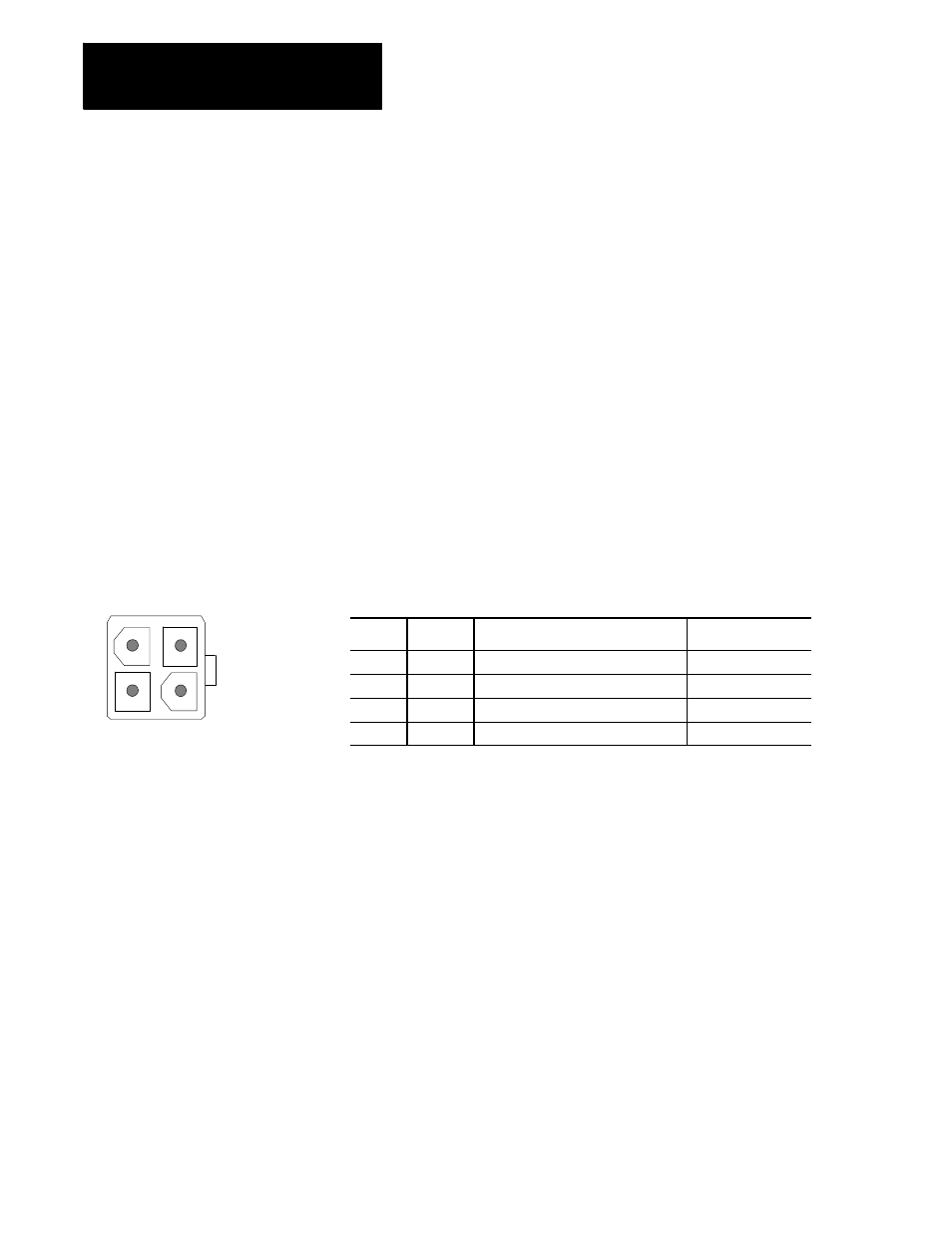
Figure 4B.17 shows an end view of connector CN23M and lists the pin
assignments.
Important: Jumper JP1 shown in Figure 4B.20 must be jumpered for
external +15V dc power if an external +15V dc power supply is used.
Figure 4B.17
Connector and Pin Assignments for the CN23M, 4 pin male, Molex 5566-4A
Pin No.
Signal
Description
Signal Destination
1
EXT_15V
External +15V dc for feedback devices
Feedback Device
2
EXT_15V
External +15V dc for feedback devices
Feedback Device
3
GND
Ground
System Common
4
GND
Ground
System Common
CN24M Servo Module +5V dc Power Supply Connector
Use connector CN24M on the optional feedback module to provide +5V dc
power to the digital servo module. Typically the optional feedback module
receives +5V dc power from the main power supply through connector
CN25M. This +5V dc power is transferred from connector CN24M on the
optional feedback module to connector CN13 on the digital servo module
using cable C43 that is supplied with the optional feedback module.
Figure 4B.18 shows an end view of connector CN24M and lists the pin
assignments of this connector.