3a.7.4 digital servo amplifiers – Rockwell Automation 8520 9/Series CNC Integration Maintenance Manual Documentation Set User Manual
Page 113
Section 3A
Primary 9/230 Components
3A-30
Two versions of the 9/230 digital are available which interface to the 8520
digital amplifier or the 1394 digital amplifier. Do not attempt to interface
an 8520 digital 9/230 to a 1394 drive or a 1394 digital 9/230 to an 8520
digital drive. These two systems are mutually exclusive.
Both the 1394 and 8520 digital servo amplifiers receive an “Axis enable”
signal and returns a “Drive OK” signal from/to the 9/230 digital CNC
provided certain system and motor tests are successful.
Important: The digital servo amplifier should be separated or isolated
from the processor module because of the electrical noise it generates.
Refer to page 7A-1 for unit mounting spacing and other noise prevention
techniques that will have to be followed when installing 8520 digital
amplifiers. Refer to your 1394 Amplifier documentation for details on
installing 1394 drive systems.
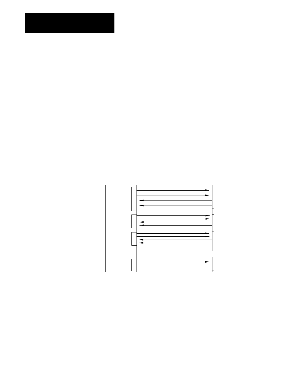
Figure 3A.21 shows the interface between the digital servo interface and
the servo amplifier.
Figure 3A.21
Digital Servo Amplifier Interface
9/230 Digital
J1
J2
J3
ANALOG OUT
Servo
Amplifier
CNA1 or
CNC1
(Axis 1)
CNA2 or
CNC2
(Axis 2)
CNA3 or
CNC3
(Axis 3)
Spindle
amplifier
Drive Signal
Axis enable
Status
Velocity signal (analog)
11089-I
Feedback (1394 only)
Important: The configuration of the digital servo module output ports
with the digital servo amplifier connectors will vary depending on the
AMP configuration of the system. Refer to the 9/Series CNC AMP
Reference Manual, publication 8520-6.4, for more information.
3A.7.4
Digital Servo Amplifiers