Rockwell Automation 8520 9/Series CNC Integration Maintenance Manual Documentation Set User Manual
Page 628
Section 12
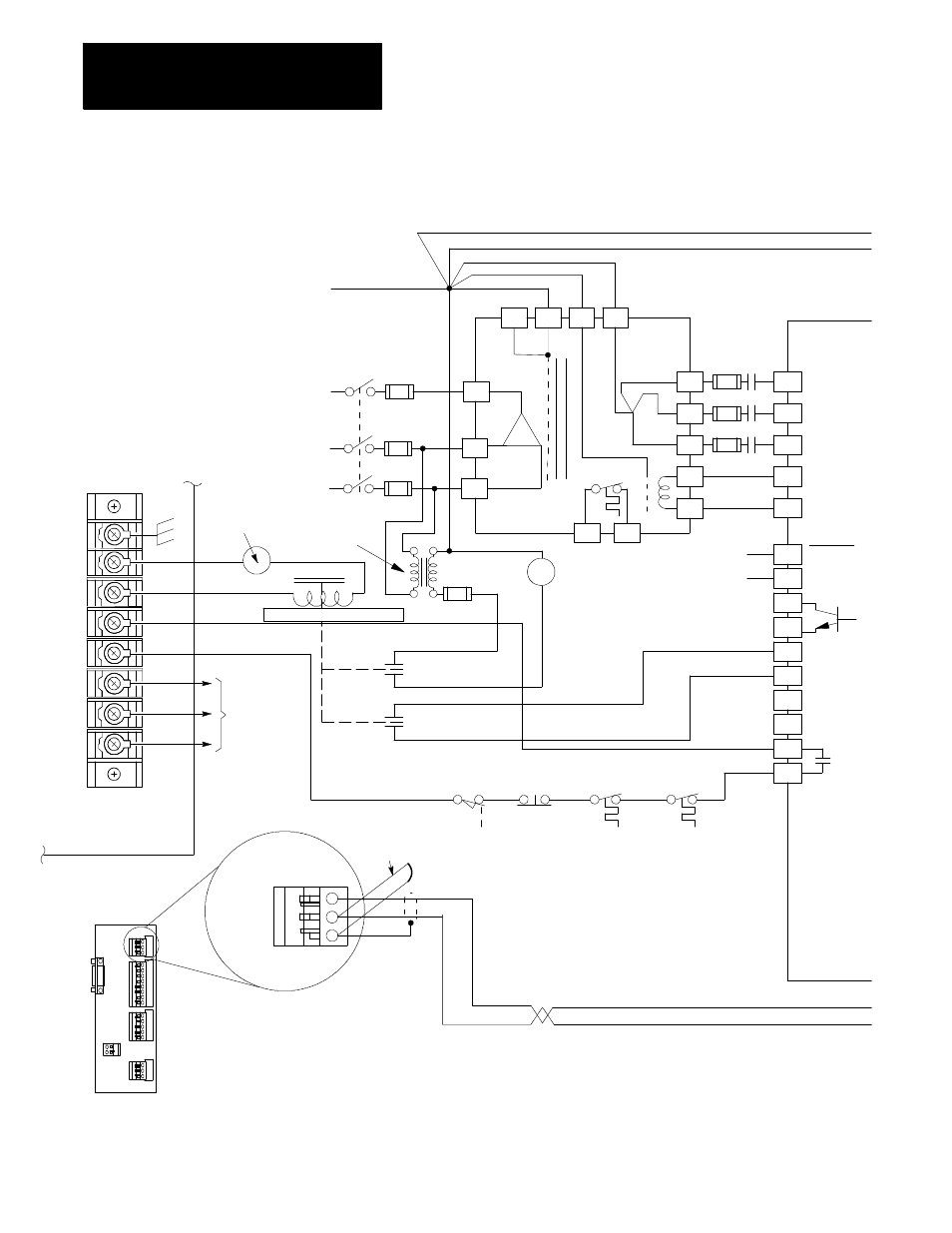
Wiring A-B Analog Drives
12-6
Figure 12.5
Wiring Diagram For Series 1389 Drives
H1
H4
H7
G2
G1
G0
X0
P1
P2
X1
X2
X3
Y1
Y2
M1
TB2 -- 1
TB2 -- 2
TB2 -- 3
TB2 -- 4
TB2 -- 5
TB2 -- 6
TB2 -- 7
TB2 -- 8
TB2 -- 9
TB2 -- 10
1389 Isolation
Transformer
F
120V
MT
TS
TB1 -- 1
TB1 -- 2
TB1 -- 3
TB1 -- 7
TB1 -- 8
230V
M1
M1
230V ac
M1
ac
7
6
5
4
Reset 3
Common 2
E-STOP 1
DRIVE
DRIVE
DR RET
SHLD
Connection
to MTB Panel
E-STOP
and
E-STOP
Reset
1771 HTE
Encoder
Termination
Panel
Velocity Command
+ Ref
-- Ref
E-STOP
String
Axis
Overtravel
(Extreme)
Remote
E-STOP
T1
T2
Motor
Thermal
Switch
(see T1, T2 on
Bulletin 1326
Servo Motor)
P1
P2
Transformer
Thermal
Switch
(see P1, P2
above)
Power
Supply
System Ground
Main Disconnect/Fuses
+240/480V ac
3 phase
Control
Transformer
Thermal
Transformer
Switch
Frame
Reset
Reset Return
Enable Source
Enable Source
Enable Source
Enable Source
System
OK
Bus UV
(isolated)
A
B
C
D
E
F
E-STOP status relay
Status
relay
power
C
O
N
T
I
N
U
E
D
O
N
N
E
X
T
P
A
G
E
NOTE:
1. We recommend installation of this connection. Remove it if
excessive noise from chassis ground occurs.
2. The connection from the termination panel to the drive should
be as short as possible. We recommend less than 20 ft.
Note 1
Note 2
11372-I
ac
Motherboard (9260 and
9/290) or Processor Board
(9/230) terminal block BT1
If your control has terminal 8,
then connect it to chassis ground.
If terminal 8 is not present on
your control, then this type of
grounding is not necessary.
8