13a.9.2 absolute encoder feedback interface – Rockwell Automation 8520 9/Series CNC Integration Maintenance Manual Documentation Set User Manual
Page 666
A
B
C
D
E
F
G
H
J
L
M
N
P
R
S
T
K
Section 13A
Connecting 8520 Digital Drive Systems
13A-32
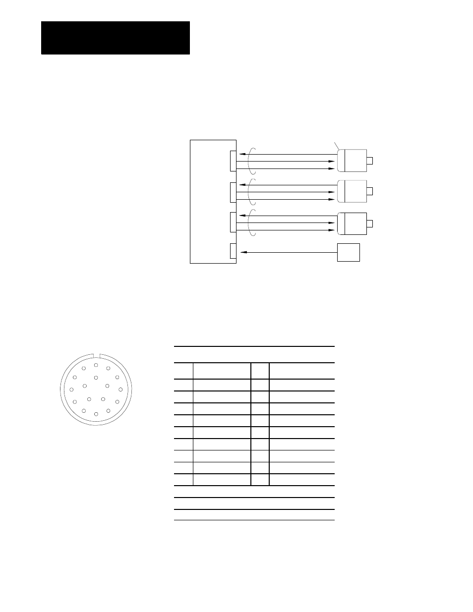
Figure 13A.7 shows the interface between the 8520 digital servo module
and the 8500 digital servo motors with absolute encoders.
Figure 13A.7
Absolute Encoder to 8520 Digital Servo Module Interface
Feedback device
(Absolute encoder)
Channel signals (A, B, Z)
Power supply (+5V dc)
Battery (+V dc)
Servo
motor
1
Servo
motor
2
Servo
motor
3
Battery
11093-I
Servo Connector
Servo Connector
Servo Connector
Battery
Connector
Servo module or 9/230 CNC
Figure 13A.8 shows the connector and lists the pin assignments used to
interface the absolute encoder with the 8520 digital servo module.
Figure 13A.8
Absolute Encoder Feedback Connector and Pin Assignments
Absolute Encoder
Pin
Signal
Pin
Signal
A
A Channel Output
K
--------------------------------
B
/A Channel Output
L
--------------------------------
C
B Channel Output
M
--------------------------------
D
/B Channel Output
N
--------------------------------
E
Z Channel Output
1
P
--------------------------------
F
/Z Channel Output
1
R
Encoder Reset Pin
G
0V
S
0V (battery)
H
5V (power supply)
T
+V (battery)
J
Frame Ground
--
--------------------------------
Connector Type: Cannon MS3102A20-29P
Signal Output Circuit: Differential Line Driver
1
The Z channel output is used for the marker signal
13A.9.2
Absolute Encoder Feedback
Interface