Rockwell Automation 8520 9/Series CNC Integration Maintenance Manual Documentation Set User Manual
Page 382
Section 7A
Connecting Components
7A-34
Table 7A.A
Cable and Connector List (continued)
Cable No.
Control
From Module and Connector
Cable Name
To Module and Connector
Cat. No.
C19
9/230, 9/260
and 9/290
8520 Digital Servo Amplifier
TB1, TB4
8520 Digital Servo Motor
Power Cable (230V ac)
8520 Digital Servo Motor
Power Connector
Prepared by Customer
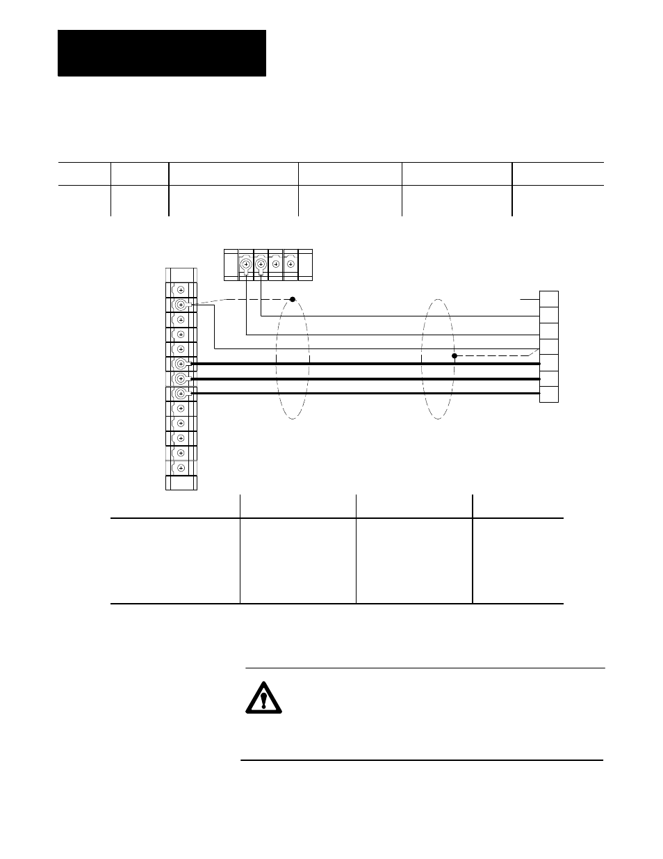
Example for the 2AX--D Amplifier connections to motor one (Series A or B, without brake)
1
2
3
4
5
6
7
8
9
10
11
12
13
1 2 3 4 TB4
C19
TB1
G
F
E
D
C
B
A
Thermal Protector
N.C.
Shield
Tie Shield to ground at both TB1 and Servo Motor
3 conductor 12 Ga. -- Motor
2 conductor 16 Ga. -- Thermal
1 conductor 16 Ga. -- Ground
2 conductor 16 Ga. -- not used
1 Shld.
For 1326-CB-AB 12 Ga.
Connector On End of Cable
Cable Type
Connector On End of Cable
Max. Cable Length
Miscellaneous
10 Ga. (TBD)
12 Ga.
1326-CP-AB100 (100 ft)
” ” -AB200 (200 ft)
” ”
”
”
1326-CP-AB1500 (1500 ft)
(E24-10S)
(8520-BC7F)
MS Style E20-15S 8520-ac7F
20m (65 ft)
An example of the 2AX-D 8520 digital servo amplifier connection to an A
and B series 8520 digital servo motor with brake is shown in the next cable
drawing.
ATTENTION: The pin layout and pin assignments of the
connector on the A series servo motor with brake are different
than the pin layout and pin assignments of the connector on the
B series 8520 digital servo motor with brake. Refer to appendix
B for additional information.