Rockwell Automation 8520 9/Series CNC Integration Maintenance Manual Documentation Set User Manual
Page 661
F
A
B
G
E
D
C
Section 13A
Connecting 8520 Digital Drive Systems
13A-27
The 8500 digital servo motor leads must be connected as shown below.
The servo motor rotation, as viewed from the shaft end, will depend on the
value of the SIGN OF FEEDBACK AMP parameter. Refer to the
9/260-9/290 AMP Reference Manual, publication 8520-6.4, for more
information.
Important: The A series 8500 digital servo motor connector (without
brake) is slightly smaller than the B series servo motor connector (without
brake). The pin layout of these connectors is the same.
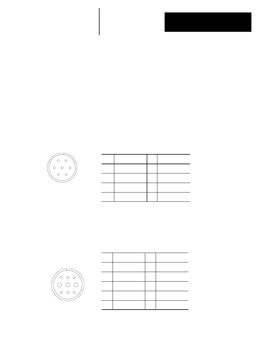
Figure 13A.2 lists the pin assignments for the 8500 digital servo motor
connector without brake.
Figure 13A.2
A and B Series 8500 Digital Servo Motor Connector Pin Assignments
(without brake)
Pin
Signal
Pin
Signal
A
PHASE A (U)
E
Thermal Protector
B
PHASE B (V)
F
Thermal Protector
C
PHASE C (W)
G
D
Ground and Shield
--
Figure 13A.3 shows the pin layout for the A series 8500 digital servo
motor connector with brake.
Figure 13A.3
A Series 8500 digital Servo Motor Connector Pin Assignments (with
brake)
Pin
Signal
Pin
Signal
A
--
F
Phase A (U)
B
Phase C (W)
G
Thermal Protector
C
Brake Terminal
H
Thermal Protector
D
Brake Terminal
I
Phase B (V)
E
Ground and Shield
Important: The A series 8500 digital servo motor connector (with brake)
is slightly smaller and its pin layout is different than the B series 8500
digital servo motor connector (with brake).
13A.8.2
8500 Digital Servo Motor
Connector and Pin
Assignments
F
I
E
D
C
B
A
H
G