Power distribution – Rockwell Automation 8520 9/Series CNC Integration Maintenance Manual Documentation Set User Manual
Page 122
Section
3B
3B-1
Power Distribution
Once you have planned your system layout, you can begin connecting
power and components to your system. In this section we discuss:
how ac power is distributed through the system
connecting the main power supply and operator interface power supply
main and operator panel power supply input power specifications
protective grounding
The external ac power connections to the control and operator panel are
covered in this section. For information on external ac power source
connections to servo amplifiers, servo motors, and I/O modules, refer to
the sections that cover these components. For details on external ac power
source connections to an analog servo amplifier or analog servo motor,
refer to the documentation provided by the manufacturer.
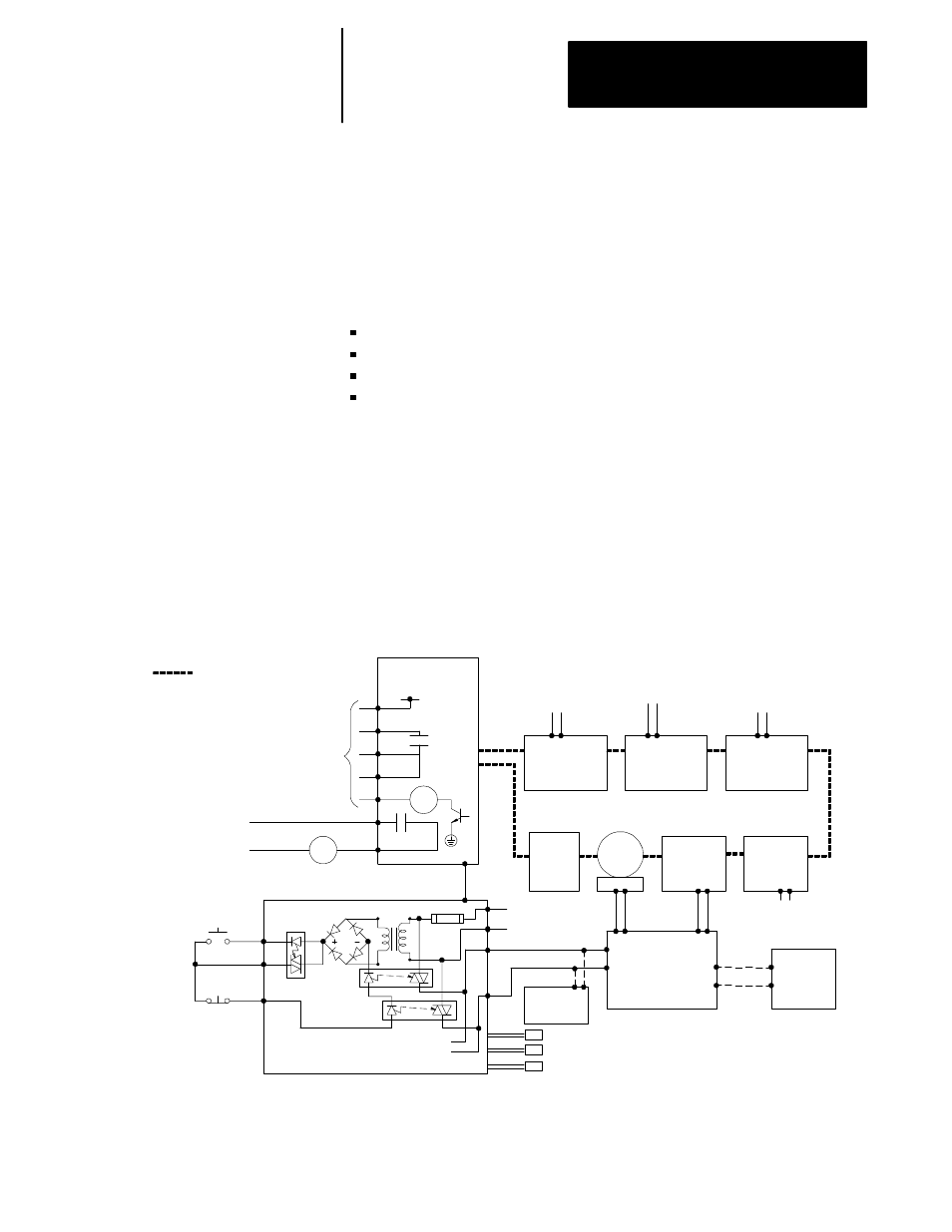
Figure 3B.1 shows the power distribution from the supply to the control
and its components.
Figure 3B.1
Power Distribution from the Supply to the Control and its Components
115/230V ac
Customer supplied
24V dc
115/230V ac
Digital I/O
E151/E152/E153
Digital I/O
E154
Analog I/O
I/O Ring
E-Stop
1746
I/O
ring
adapter
Customer supplied
24V dc
MTB
I/O
1
HPG
High
density
I/O
12V dc
5V dc
Operator panel
power supply
2
12V dc
Mono-
chrome
monitor
Color
monitor
115/230V ac
Auxiliary ac
To power circuitry
115/230V ac
ac input
Cable C04
P1
Off
button
On
button
Low current
( < 1.0 amp) pilot relay
K1
24V dc
Customer supplied1
OFF
COM
ON
Main power
supply
8A Fuse
CN07
2
3
4
5
6
7
K
1A
K
1B
5V dc connectors to servo modules (encoder power)
(9/260 and 9/290 only)
11194-I
9/230 CNC
Indicates fiber optic cable
1
May not be necessary on PS2 24V is part of the power supply.
2
May be mounted on operator panel or portable operator panel interface assembly.
3B.0
Section Overview