Rockwell Automation 8520 9/Series CNC Integration Maintenance Manual Documentation Set User Manual
Page 51
Section 2A
Planning Your System Layout
2A-6
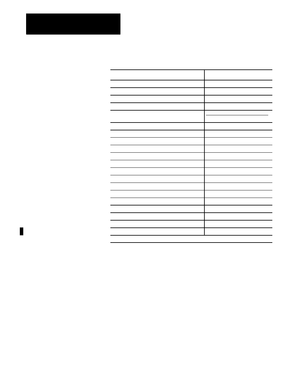
Table 2A.B
Component and Module Heat Generation Wattages
Component or Module
Heat Generation Wattage (W)
9/230 and Main Power Supply
130
9/260 or 9/290 and Main Power Supply
225
9/440 CNC/1394 Drive 5kw System Module
(@100%)
80
9/440 CNC/1394 Drive 10kw System Module
(@100%)
98
9/440 Axis Modules/1394 Drive
(each module @100%)
AM03
AM04
AM07
AM75
48
63
93
346*
9/440 CNC Power On/Off Control Module
5
Portable Operator Panel Interface Assembly
72
Monochrome Operator Panel
125
Color TFT Operator Panel (flat panel)
55
Color CRT Operator Panel
175
MTB Panel
15
HPG
1.2
3-axis Digital Servo Module
13.5
3-axis Analog Servo Module
14
4-axis Digital Servo Module (8520-ENC4)
15
4-axis Analog/1394 Servo Module (8520-SM4)
14
1746I Ring Adaptor (module only)
0.9
1771-HTE Termination Panel
0
MTB Panel I/O Module
5
Remote I/O Module (8520--RIOM)
4.2
* 18 Watts in cabinet, 328 Watts out through cabinet heat sink
The temperature rise inside a metallic cabinet incorporating only an
internal convection cooling fan can be roughly calculated with the
following formula:
T = W/6S
- T = Temperature rise in cabinet (
°
C)
- W = Heat generation (Watts) by units and modules
- S = Heat radiation surface area (sq. meter) of cabinet
(total cabinet surface area minus any area in contact with the floor or
building wall)
The above equation assumes a closed cabinet with heat dissipated only
through cabinet radiation.