15a.4.2 high density i/o – Rockwell Automation 8520 9/Series CNC Integration Maintenance Manual Documentation Set User Manual
Page 725
Section 15A
Troubleshooting the Control
15A-15
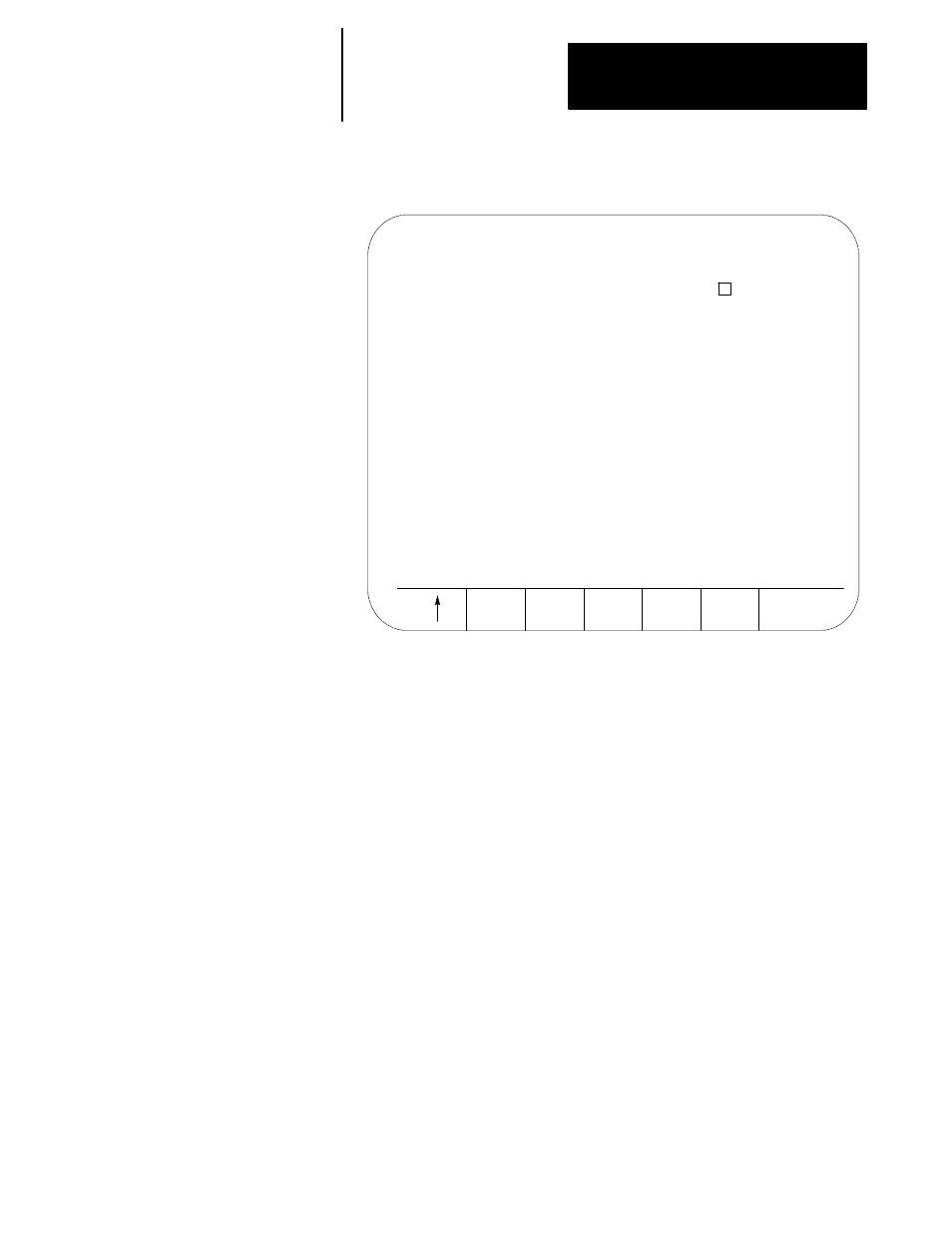
Figure 15A.2
Digital I/O Diagnostics Screen
DIGITAL I/O
SETUP MODE
DEVICE NO. 02
ON =
IN A
01 02 03 04 05 06 07 08 09 10
IN B
01 02 03 04 05 06 07 08 09 10
OUT A
11 12 13 14 15 16
OUT B
11 12 13 14 15 16
The device number of the selected Digital I/O appears under the
“DIGITAL I/O” heading. This will be a decimal number from 00 to 63.
This screen displays the inputs and outputs that correspond to the terminal
numbers on the Digital I/O. These are IN A (1 through 10), IN B (1
through 10), OUT A (11 through 16) and OUT B (11 through 16).
If an input or output is “ON”, its terminal number appears in inverse video.
This is a real time display, and its response is limited only by delays in
screen updates.
If more than one Digital I/O device is on the I/O Ring, a diagnostics screen
for each of these devices can be displayed. To display a diagnostics screen
for the next digital I/O on the ring, press and hold the [SHIFT] key and
press the [DOWN-ARROW] key.
Pressing the exit softkey (up arrow) at any time displays the Ring I/O
Menu screen.
If a High Density I/O device is selected on the Ring I/O screen and the
{DISPLY} softkey is pressed, the High Density I/O Diagnostics screen
appears. Figure 15A.3 is an example of this screen.
15A.4.2
High Density I/O