Rockwell Automation 8520 9/Series CNC Integration Maintenance Manual Documentation Set User Manual
Page 303
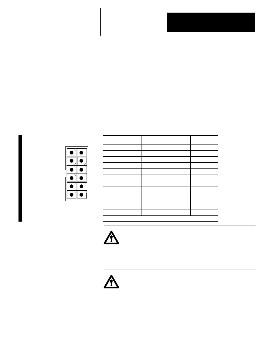
12
10
8
6
4
2
11
9
7
5
3
1
View of connector
on the end of the
feedback cable
Section 5B
9/440HR CNC/Drive System
5B-13
Important: Not all system modules have each of the eight feedback ports
enabled. The number and type of available feedback ports supported on
your 9/440HR system are defined by the options you purchased through
the factory. To determine which of the eight feedback ports are enabled on
your system, refer to page 5B-2.
Important: The 9/440HR feedback device is capable of achieving a
maximum of 2,097,152 cnts/mm (53,267,660.8 cnts/in.). Exceeding this
number of feedback counts forces your system into E--Stop, causing an
error message to display.
Figure 5B.5
Connecting the 1326 HIPERFACE Motor- mounted Devices on the 9/440HR
CNC/Drive
Pin
Signal
Description
Wire Color
1
Overall Shield
PE
Green/Yellow
2
Supply GND
Encoder Supply Ground
White
3
Supply Power
Encoder Supply Power
1
Black
4
Wire Pair Shield
PE
Clear
5
RS485_LO
Serial Data Low
Green
6
RS485_HI
Serial Data High
Black
7
Wire Pair Shield
PE
Clear
8
CHB_LO
Feedback Device Channel B Low
Black
9
CHB_HI
Feedback Device Channel B High Blue
10
Wire Pair Shield
PE
Clear
11
CHA_LO
Feedback Device Channel A Low
Black
12
CHA_HI
Feedback Device Channel A High Red
1
HIPERFACE devices (J1--J4) use 9.7V. A quad B devices (J9--J12) use 5Vdc.
ATTENTION: You cannot mount an auxiliary feedback device
to the rear of a 1326AB motor. By removing the back cover of
the motor, you will void the motor warranty and possibly
permanently disable it.
ATTENTION: Only auxiliary feedback devices are
replaceable. HIPERFACE devices are permanently mounted by
the factory and should not be removed. By removing it, you
will void the warranty and possibly permanently disable it.