Rockwell Automation 8520 9/Series CNC Integration Maintenance Manual Documentation Set User Manual
Page 443
Section 8
Communication Interface
8-10
1.
The peripheral (DTE) turns on the RS signal to notify the control
(DCE) that there is data to be transmitted.
2.
The control turns the CS signal ON to notify the peripheral that it is
ready for data reception.
3.
The peripheral begins transmitting data to the control.
4.
If the control buffer cannot accept the data, the control turns the CS
signal OFF to notify the peripheral to stop data transmission.
5.
The peripheral, upon recognizing that the CS signal has been turned
OFF, stops data transmission within two characters.
6.
The control turns the CS signal ON when it can receive data again.
7.
The peripheral, upon recognizing that the CS signal has been turned
ON, begins data transmission.
8.
After transmitting all data to the control, the peripheral turns the RS
signal OFF to notify the control that all data has been transmitted.
9.
The control turns the CS signal OFF
Data Transmitting Sequence
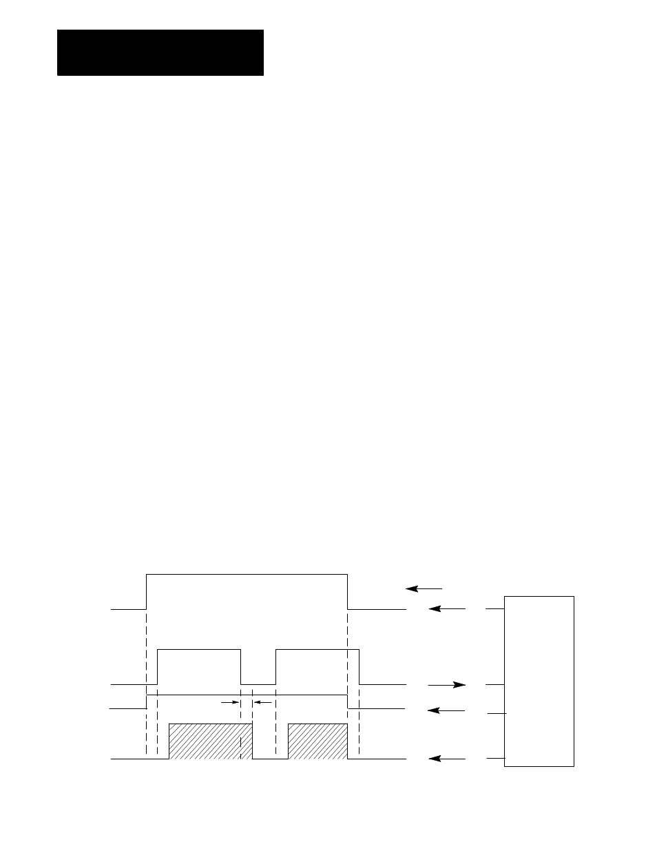
When the control transmits data to a peripheral, CS and RS signals are
used to control the communication, see Figure 8.11. The control confirms
that the peripheral is ready for data reception by the TR signal before it
transmits the data.
Figure 8.11
Data Transmitting Sequence
Signal flow
Peripheral
1 2 3
4 5
6 7
9
8
CNC
RS
RD
11355-I
CS
Pin 5
Pin 4
Pin 6
Pin 3
DM
1
1
Port B only