Rockwell Automation 8520 9/Series CNC Integration Maintenance Manual Documentation Set User Manual
Page 816
Section 15B
Replacement Procedures
15B-60
Important: Though the FLASH and RAM SIMMs can be plugged into the
same sockets they are not identical or interchangeable chips. Make sure
you label these SIMMs so they are returned to the correct sockets.
Important: Make sure when you re-install the 9/Series option chip that the
chip is oriented properly. Pin one (marked with a dot on the option chip) is
oriented towards the top left corner of the processor board.
The 9/440 system E-Stop String fuse is located on the 9/440 CNC
processor board. You must remove the 9/440 CNC assembly to replace
this fuse. Follow the procedure on page 15B-58 titled Replacing the 9/440
System Module up to and including the removal of the CNC interface
assembly.
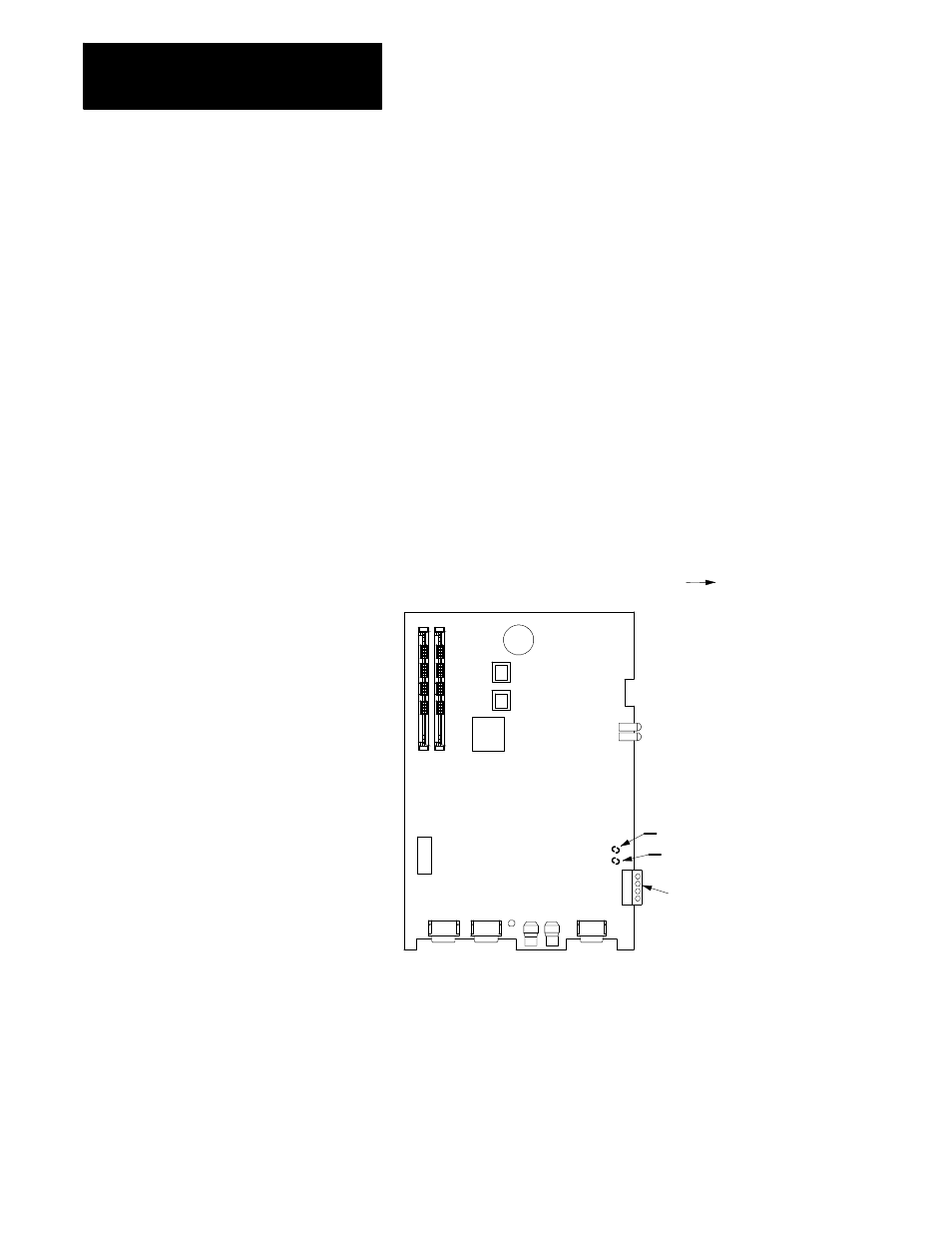
The E-Stop string is a 12V dc string protected by a .25 AMP 115 V fuse
located on the 9/440 CNC processor board. A spare fuse is also included
on this board. Contact your Allen-Bradley sales representative for details
on purchasing additional replacement fuses.
CNC Processor Board
Front of
System Module
E-Stop Connector TB1
1/4 AMP E-Stop String Fuse
1/4 AMP fuse (spare)
Remove the fuse by grasping the plastic cap and pulling straight up away
from the CNC processor board.
END OF SECTION
15B.41
Replacing the 9/440 E-Stop
String Fuse