Rockwell Automation 8520 9/Series CNC Integration Maintenance Manual Documentation Set User Manual
Page 150
Section 4B
Connecting the 3-axis Servo Module
4B-4
The 8520 digital Servo Amplifier translates low-level PWM signals from
the 8520 digital servo module to the power levels necessary to drive the
servo motors.
Current feedback data is read from the current sensors in the 8520 digital
servo amplifier and returned to the 8520 digital servo module. This data is
processed by the servo module to maintain velocity and position control,
according to module, AMP, and part program constraints.
Important: In order to use the solid tapping feature that is available on the
9/260 and 9/290 CNC, you must use the Allen-Bradley 8510 AC spindle
drive system.
Position and velocity data are read from a feedback device that is mounted on
the servo motor. This feedback device generates differential signals that are
then fed to the 8520 digital servo module. If the spindle motor uses an
encoder, it will supply spindle position feedback to the 8520 digital servo
module.
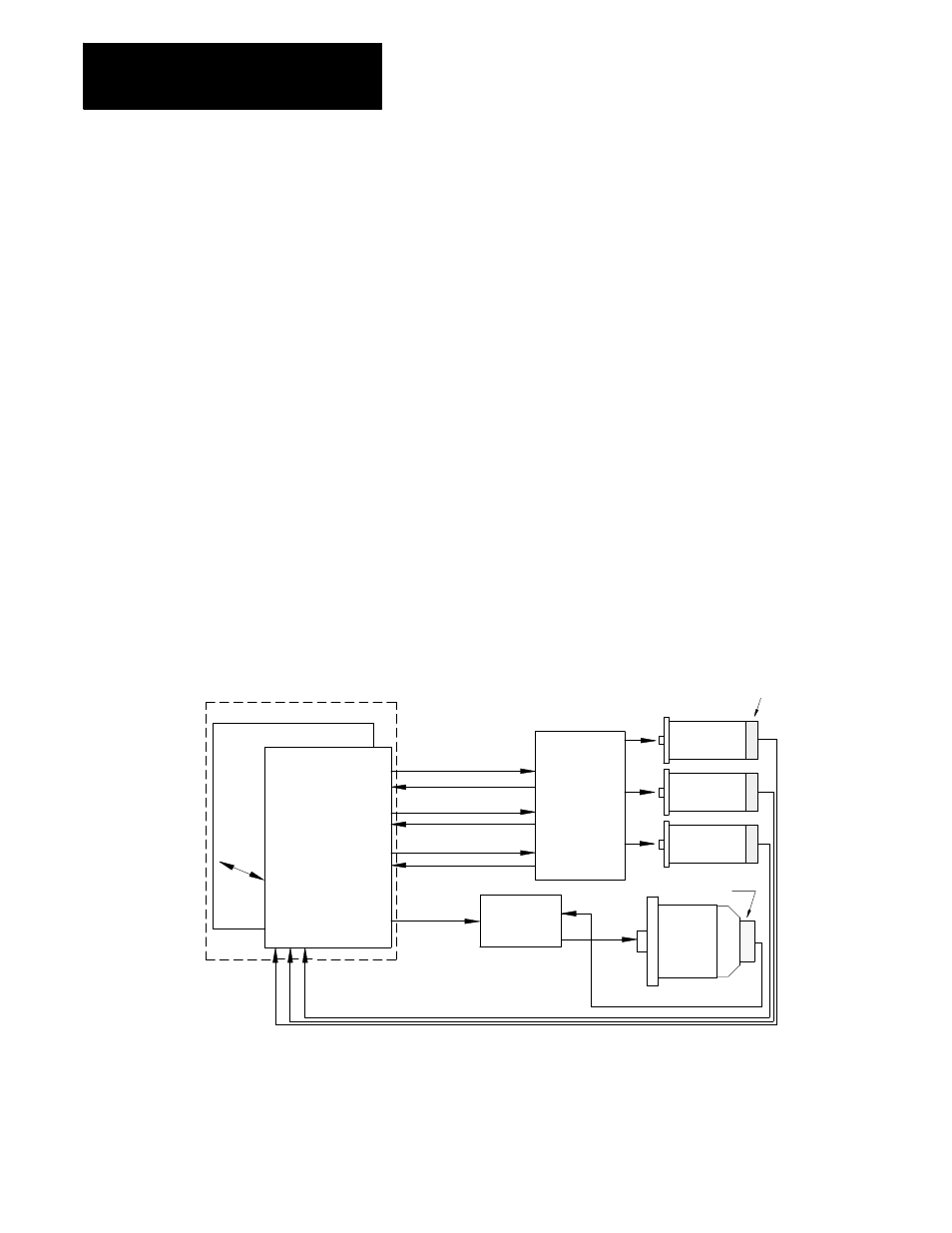
Figure 4C.1 and Figure 4C.2 show typical 8520 digital servo drive
configurations for a mill and a lathe. Refer to the 9/Series CNC 9/230,
9/260, and 9/290 AMP Reference Manual, publication 8520-6.4, for
specific details on configuring axes, axis positioning loops, and axis port
selection.
Figure 4B.3
Typical 8520 Digital Servo Drive Configuration for a Mill
Servo Module
(configured for
three axes and
one open loop
spindle)
9/260 or 9/290
Cabinet or enclosure
Spindle
drive
Spindle
motor
Servomotor
(Axis 1)
Servomotor
(Axis 2)
Servomotor
(Axis 3)
Position feedback
Servo
Amplifier
Velocity feedback
Feedback
device
Feedback device
(3 Axis
amplifier)
Analog signal
Servo drive signal (Axis 1)
Current feedback (Axis 1)
Servo drive signal (Axis 2)
Current feedback (Axis 2)
Servo drive signal (Axis 3)
Current feedback (Axis 3)
8520 digital
11274-I