11a.2 resolver feedback – Rockwell Automation 8520 9/Series CNC Integration Maintenance Manual Documentation Set User Manual
Page 608
Section 11A
Connecting 1394 Digital Drive Systems
11A-3
The 1326 servo motors that interface to the 1394 drive rely on resolvers
mounted directly to the motor for proper commutation. For these resolvers
to be properly interfaced to the 9/Series CNC their feedback must be
converted to an A quad B signal. This is accomplished by the CNC
interface board which takes the resolver feedback from the wiring board
and converts it into an A quad B signal before sending this signal on to the
9/Series CNC.
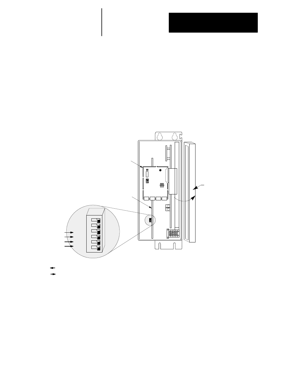
A dip switch (SW1) on the CNC interface board determines the number of
encoder counts per revolution this resolver feedback is translated into. The
bottom four switches of dip switch SW1 selects between 8192 or 32768
counts per motor revolution as follows:
Switch SW1
Left (away from Interface Board) = 32768 counts
Right (towards interface board) = 8192 counts
CNC Wiring Board
CNC Interface Board
System Module
ASRN 0
ASRN 1
FB3
FB2
FB1
FB0
Open Cover
Press Cover
Release to Open
These switches set the number of counts per/rev for each feedback device
connected to this 1394 drive. CNC1 corresponds to the feedback device
connected to FB0, CNC2 corresponds to the feedback device connected to
FB1, etc.. You must also indicate your dip switch selections by selecting
the appropriate number of counts per motor revolution in AMP for each
servo.
11A.2
Resolver Feedback