3a.1.1 connections on the processor board, Port b – Rockwell Automation 8520 9/Series CNC Integration Maintenance Manual Documentation Set User Manual
Page 86
Section 3A
Primary 9/230 Components
3A-3
Table 3A.A lists the connections on the 9/230 processor board and where
to locate the cable diagrams within this manual. Refer to page 7A-1 for
detailed cable drawings.
Table 3A.A
Locating Wiring Diagrams for the 9/230 Processors
Attach this connector:
To:
Use this Cable
Lithium Battery (P1)
Lithium Battery Pack
C13,
I/O Ring Output (Red)
First Device on I/O Ring
C10
I/O Ring Input (Black)
Last Device on I/O Ring
C10
E-Stop (TB1)
E-stop String
C05, C06
Port B (J7)
Peripheral Devices
C07
Video (J8)
Operator Interface
(Color or Monochrome)
C09
TP (TB2)
Touch Probe
C46
Analog Out (TB3)
Spindle
C42
Analog Servo Connector
(J1, J2, or J3)
Termination Panel
C36
Digital Servo Connector
(J1, J2, or J3)
Servo System
C18, C20
Power Supply (P12)
Power Supply
C04
Port B
Serial port B is used to transmit data to and from peripheral devices. It can
be wired for RS-232 communications or RS-422 communications.
Softkey selections on the controls operator panel now selection at the
specific device protocol to be used.
The MTB panel may have the optional serial interface connector mounted
on it. This connector provides an external interface port for RS-232 or
RS-422 interface from a peripheral to the control. It connects to port B
with cable C07. Refer to the “Cable List” section on page 7A-1 for
additional information on cable C07. For more information on the signals
of each pin, refer to page 8-1.
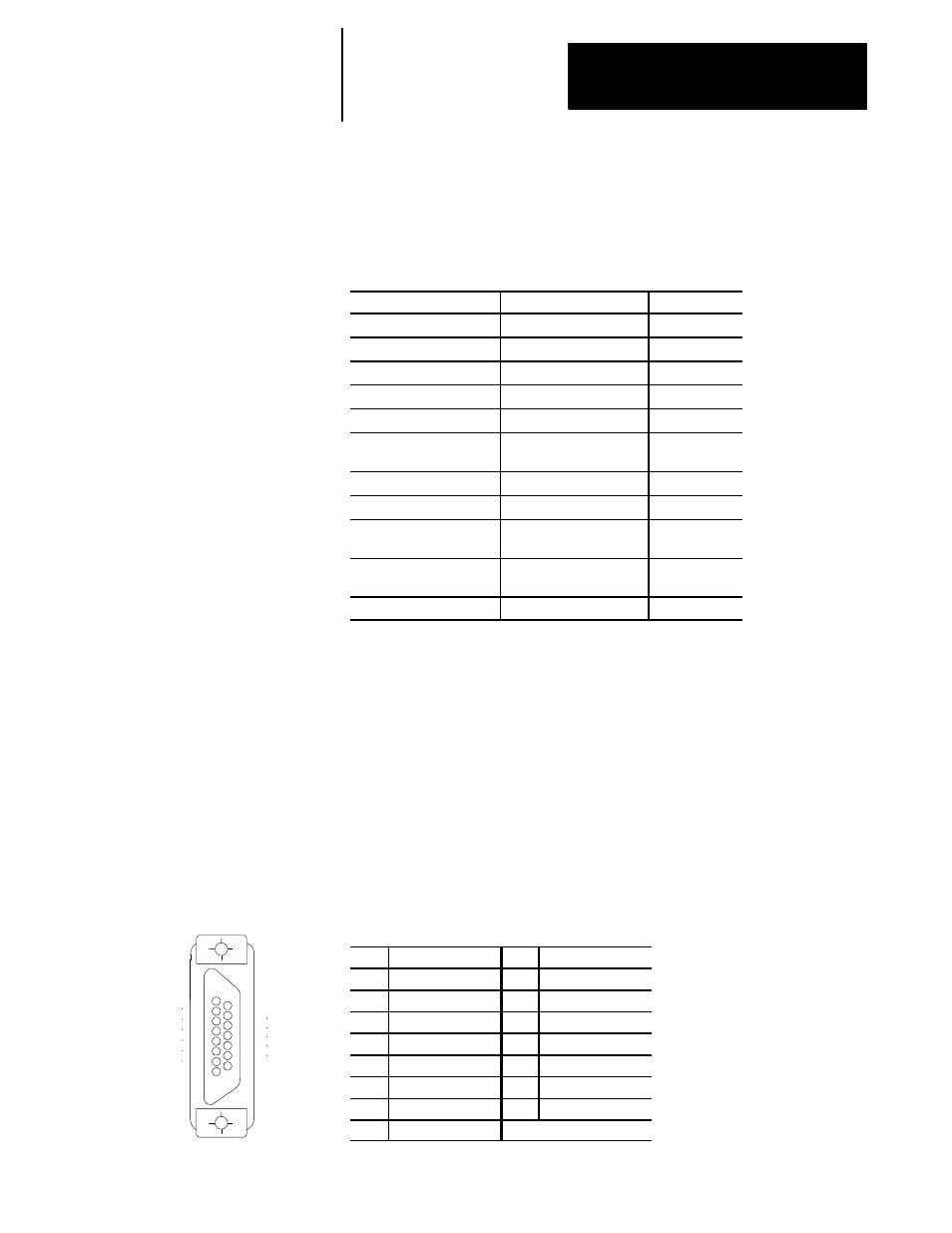
Figure 3A.3
Port B-J7 (has pin sockets) and Pin Assignments
Pin
Assignment
Pin
Assignment
1
Chassis GND
9
Send Data B
2
Send Data A
10
Receive Data B
3
Receive Data A
11
Request to Send B
4
Request to Send A
12
Clear to Send B
5
Clear to Send A
13
Data Set RDY B
6
Data Set RDY A
14
Data Term RDY B
7
Signal GND
15
Not Used
8
Data Term RDY A
3A.1.1
Connections on the
Processor Board
8
1
15
9
11257-I
Port B