Rockwell Automation 8520 9/Series CNC Integration Maintenance Manual Documentation Set User Manual
Page 207
Section 4C
Connecting the 4-axis Servo Module
4C-9
Axes are connected to the D-shell connectors marked J1, J2, J3 and J4.
Axes can be connected in any order on the servo module. However, if a
spindle with feedback is configured the spindle must be connected to the
first available D-Shell connector after the last connector used by a linear or
rotary axis.
ATTENTION: With analog systems, do not insert the
plug-type ANALOG OUT terminal block (TB2) into an encoder
termination panel DRIVE terminal block or vice versa.
Although these plugs will fit together, pin assignments are
different. Switching these connections without rewiring the
plug-type terminal block may cause damage to equipment.
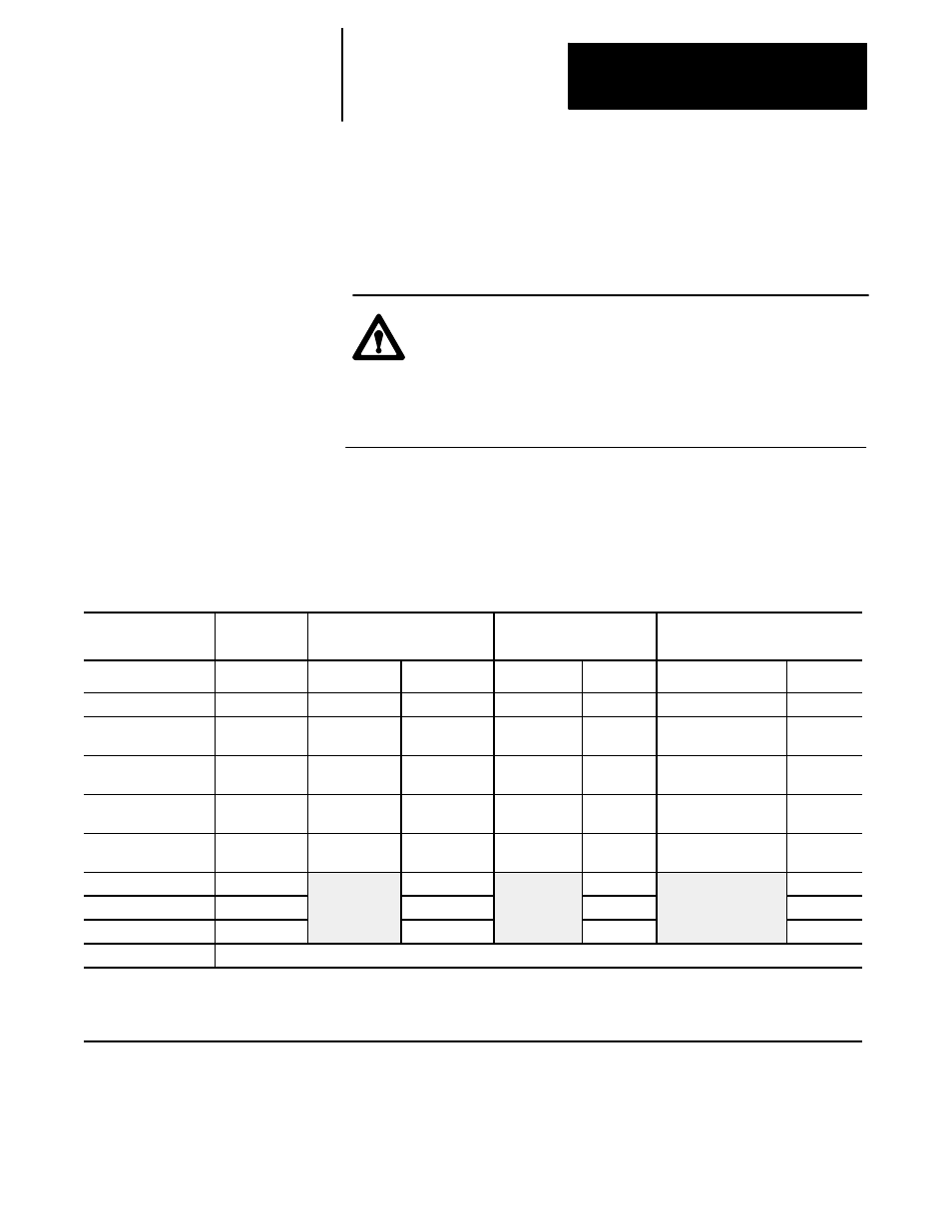
Table 4C.A lists the connectors that are used to integrate the digital servo
module with other modules of the control.
Table 4C.A
Servo Module Connectors
This Servo
Module Connector
Connects to:
8520 Drive
1394 Drive
Analog Drive
Connector
Cable No.
Connector
Cable No.
Connector
Cable No.
P1
Motherboard
P4, P5 or P6
C12
P4, P5 or P6
C12
P4, P5 or P6
C12
J1
Servo Amplifier
CNA1
C14/15
CNC1
C47
see drive’s
documentation
C36-C39
J2
Servo Amplifier
CNA2
C14/15
CNC2
C47
see drive’s
documentation
C36-C39
J3
Servo Amplifier
CNA3
C14/15
CNC3
C47
see drive’s
documentation
C36-C39
J4
Servo Amplifier
CNA4
C14/15
CNC4
C47
see drive’s
documentation
C36-C39
TB1
Spindle
C42
C42
C42
TB2
Touch Probe
C46
C46
C46
P2
Battery Pack
C24
C24
C24
P3
+5V Encoder Power Cable from Main Power Supply
Important:
When 1 servo module is used, it must be connected to P4 of the motherboard. When 2 servo modules are used, the first servo module must be connected to
P4 and the second to connector P6. When three modules are used, connect the first to P4, the second to P6 and the third to P5.
1
If a spindle incorporates an encoder to supply position feedback to the servo module, the spindle encoder must be interfaced with the last open
connector of these 3 connectors. Refer to the 9/260-9/290 AMP Reference Manual, publication 8520-6.4, for more information.
4C.5
Connecting Axes to the
Servo Module
4C.5.1
Servo Module Connectors
and Pin Assignments