4b.3.5 optional feedback module test points – Rockwell Automation 8520 9/Series CNC Integration Maintenance Manual Documentation Set User Manual
Page 169
CN21M
CN22M
CN23M
CN24M
CN25M
JP1
TP1, TP4, TP7
TP2, TP5, TP8
TP11
TP10
TP15
TP3, TP6, TP12
TP14
TP9, TP13
Rotary
Switch
11867-I
Section 4B
Connecting the 3-axis Servo Module
4B-23
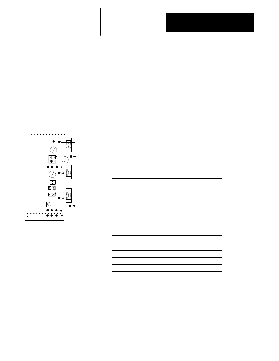
Test points are small metallic pins on the optional feedback module.
Hardware troubleshooting and testing for proper wiring can begin by
testing for proper voltage or signals at these pins.
Test points are labeled with the letters TP followed by a number.
Figure 4B.22 shows the location of each test point and lists the test data of
each test point.
Figure 4B.22
Optional Feedback Module Test Point Locations and Test Point Values
Test Point
Optional Feedback Module Voltage
TP9
+5V dc Power for Feedback Devices
TP14
+5V dc Power for Feedback Devices
TP15
+5V dc Power for Feedback Devices
TP11
+15V dc Power for Feedback Devices
TP10
GND
TP13
GND
Test Point
Servo Module Encoder Feedback Signals
TP5
A Channel
TP2
B Channel
TP8
Z Channel
TP4
U Channel
TP7
V Channel
TP1
W Channel
Test Point
Optional Feedback Device Feedback Signals
TP12
A Channel
TP6
B Channel
TP3
Z Channel
The test points of the optional feedback module can monitor the feedback
signals from one feedback port on the servo module and/or one feedback
port on the optional feedback module at one time. A rotary switch on the
optional feedback module allows the selection of which ports the test
points are monitoring. Table 4B.G lists the rotary switch positions and the
corresponding ports the test points monitor at each switch position.
4B.3.5
Optional Feedback Module
Test Points