4b.3.3 optional feedback module jumper (jp1) – Rockwell Automation 8520 9/Series CNC Integration Maintenance Manual Documentation Set User Manual
Page 167
1
2
11282-I
1
2
11282-I
Section 4B
Connecting the 3-axis Servo Module
4B-21
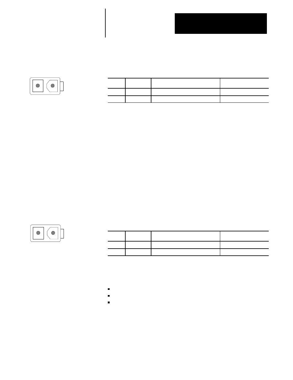
Figure 4B.18
Connector and Pin Assignments of the CN24M, 2 pin male, Molex
5566-2A
Pin No.
Signal
Description
Signal Destination
1
ENC_5V
+5V dc power for digital servo module
Digital Servo Module
2
GND
Ground
System Common
CN25M +5V dc Power Supply Connector
Use connector CN25M on the optional feedback module to connect a +5V
dc power supply to the optional feedback module. Typically the optional
feedback module receives +5V dc power from the main power supply
through connector CN25M. This +5V dc power supply powers the
encoders of the digital servo module and the non-motor mounted feedback
devices of the optional feedback module.
When the sum of the power requirements of the servo module and the
optional feedback module exceed the +5V dc output of the main power
supply, use an external power source to supply the +5V dc power.
Figure 4B.19 shows an end view of connector CN25M and lists the pin
assignments.
Figure 4B.19
Connector and Pin Assignments for the CN25M, 2 pin male, Molex 5566-2A
Pin No.
Signal
Description
Signal Destination
1
ENC_5V
+5V dc for optional feedback device
Optional Feedback Device
2
GND
Ground
System Common
Use jumper JP1 on the optional feedback module to select whether the
+15V dc power supply for the non-motor mounted feedback devices is :
supplied from the main power supply
supplied from an external power source
removed from the feedback connectors
Non-motor mounted feedback devices receive +15V dc power through pins
3 and 4 of connectors CN14F, CN15F, and CN16F on the optional
feedback module. Figure 4B.20 shows the jumper selections of jumper
JP1.
4B.3.3
Optional Feedback Module
Jumper (JP1)