Cn2, cn3, and cn4 servo drive signal connectors – Rockwell Automation 8520 9/Series CNC Integration Maintenance Manual Documentation Set User Manual
Page 154
1
2
3
4
5
6
7
8
9 10
11 12 13
14
15
16
17 18
19
20
11277-I
Section 4B
Connecting the 3-axis Servo Module
4B-8
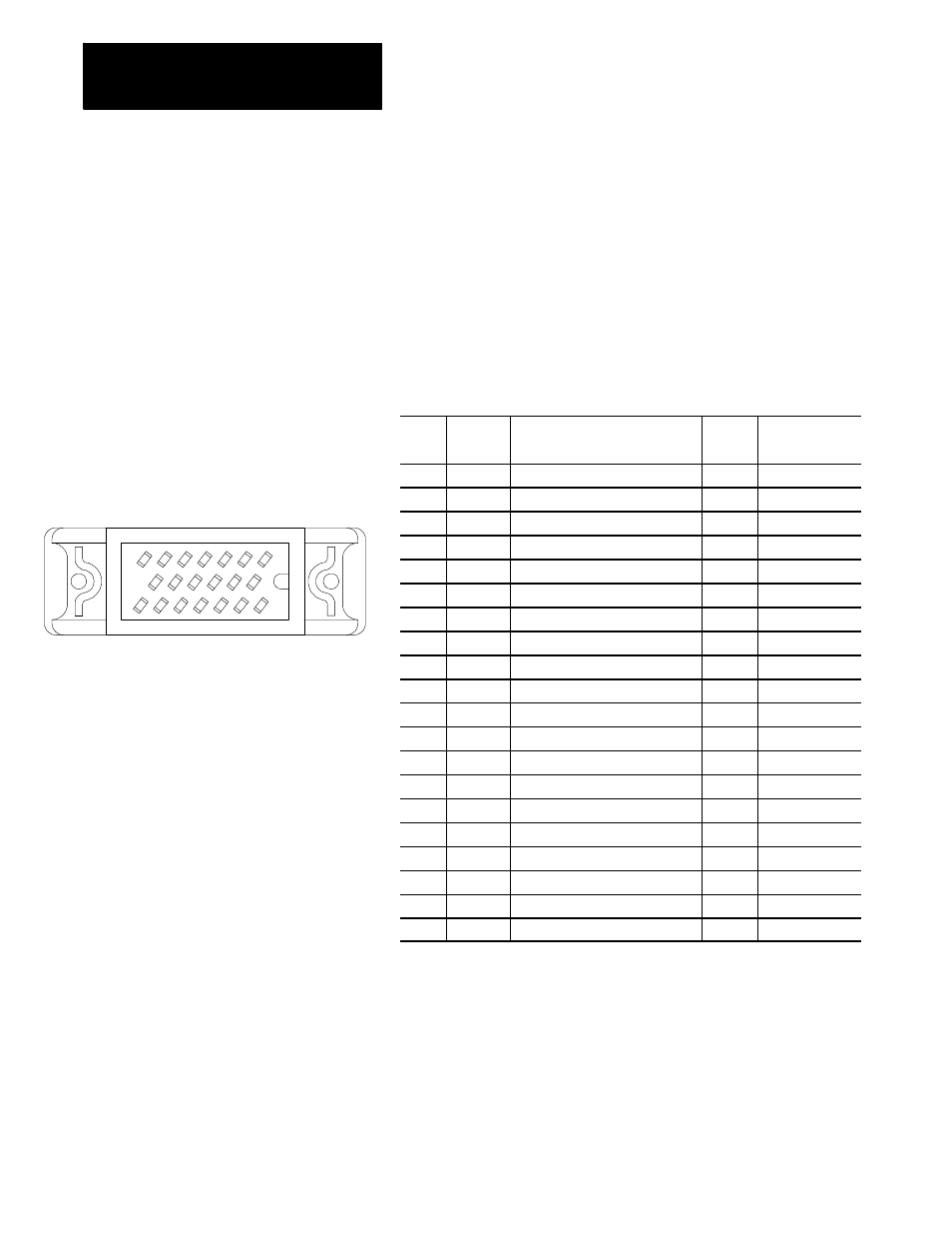
CN2, CN3, and CN4 Servo Drive Signal Connectors
The digital servo module sends servo drive signals and receives current
feedback from the servo amplifier through connectors CN2, CN3, and
CN4. Figure 4C.7 shows an end view of connectors CN2, CN3, and CN4
and lists the pin assignments of the these connectors.
Figure 4B.6
End View of Connectors and Pin Assignments of CN2, CN3, CN4, 20 pin
male, Honda MR-20RMD2
Pin
No.
Signal
Description
True
Level
Signal Destina-
tion
1
ENABLE
Motor Amplifier Enable
HIGH
Servo Amplifier
2
/ENABLE “ON”State ---- Enable (Active)
LOW
Servo Amplifier
3
Shield
Chassis ground for shielded cable
4
Shield
Chassis ground for shielded cable
5
Shield
Chassis ground for shielded cable
6
STATUS
Amplifier status flag
HIGH
Servo Module
7
/STATUS
“ON”state - normal operation
LOW
Servo Module
8
PWM_A
Current command for Phase_A
HIGH
Servo Amplifier
9
/PWM_A
Diff. signal
LOW
Servo Amplifier
10
PWM_B
Current command for Phase_B
HIGH
Servo Amplifier
11
/PWM_B
Diff. signal
LOW
Servo Amplifier
12
PWM_C
Current command for Phase_C
HIGH
Servo Amplifier
13
/PWM_C
Diff. signal
LOW
Servo Amplifier
14
Ia
Current sensing value for Phase_A
HIGH
Servo Module
15
/Ia
Diff. Signal
LOW
Servo Module
16
Shield
Chassis ground for shielded cable
17
Shield
Chassis ground for shielded cable
18
Shield
Chassis ground for shielded cable
19
Ib
Current sensing value for Phase_B
HIGH
Servo Module
20
/Ib
Diff. Signal
LOW
Servo Module