13a.9.1 incremental encoder feedback interface – Rockwell Automation 8520 9/Series CNC Integration Maintenance Manual Documentation Set User Manual
Page 665
A
B
C
D
E
F
G
H
J
L
M
N
P
R
S
T
K
Section 13A
Connecting 8520 Digital Drive Systems
13A-31
This value is then compared to the actual A channel frequency of the
encoder which is determined by the following formula:
(Lines/Rev.) x (Max. Operating RPM) x (min./60sec.)
As long as the actual encoder A channel frequency does not exceed the
maximum encoder channel frequency calculated above, the servo module
should process the encoder feedback data without a quadrature fault.
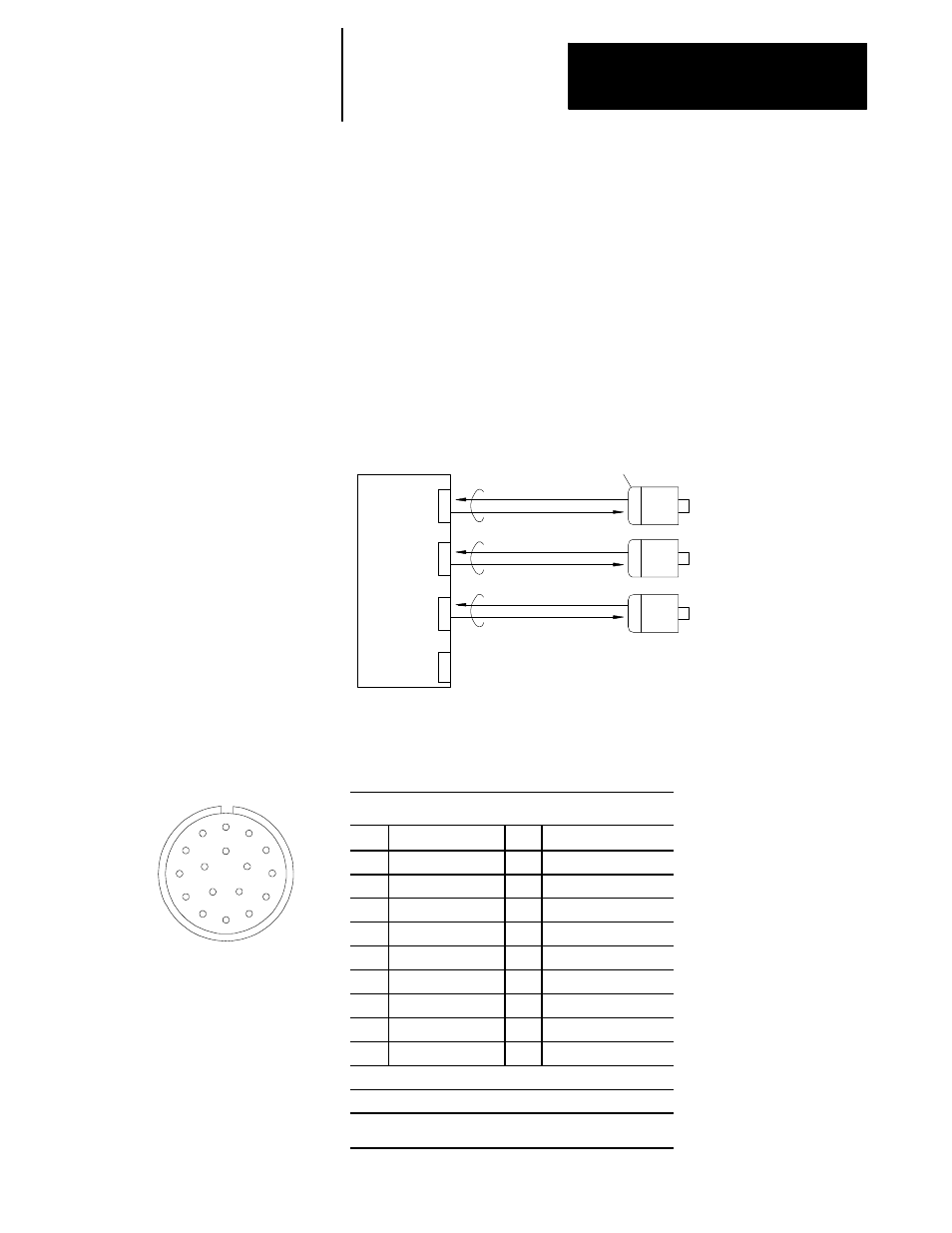
Figure 13A.5 shows the interface between the 8500 digital servo module
and servo motors with incremental encoders.
Figure 13A.5
Incremental Encoder to 8520 Digital Servo Module Interface
Feedback device
(incremental encoder)
Servo
motor
1
Servo
motor
2
Servo
motor
3
Channel signals (A, B, Z, U, V, W)
Power supply (+5V dc)
11092-I
Servo module or 9/230 CNC
Servo Connector
Servo Connector
Servo Connector
Analog Out
Figure 13A.6 shows the connector and pin assignments used to interface
the incremental encoder with the 8520 digital servo module.
Figure 13A.6
Incremental Encoder Feedback Connector and Pin Assignments
Incremental Encoder
Pin
Signal
Pin
Signal
A
A Channel Output
K
U Channel Output
2
B
/A Channel Output
L
/U Channel Output
2
C
B Channel Output
M
V Channel Output
2
D
/B Channel Output
N
/V Channel Output
2
E
Z Channel Output
1
P
W Channel Output
2
F
/Z Channel Output
1
R
/W Channel Output
2
G
0V
S
--------------------------------
H
+5V dc
T
--------------------------------
J
Frame Ground
--
--------------------------------
Connector Type: Cannon MS3102A20-29P
Signal Output Circuit: Differential Line Driver
1
The Z channel output is used for the marker signal.
2
The U, V, and W channels are used for motor phasing only
13A.9.1
Incremental Encoder
Feedback Interface