Analog out (tb2) auxiliary output connector – Rockwell Automation 8520 9/Series CNC Integration Maintenance Manual Documentation Set User Manual
Page 181
AN
AL
O
G
3
2
1
O
UT
AX
IS
AN
AL
O
G
BA
T/
TP
RUN
\FL
T
FBF
LT1
FBF
LT2
FBF
LT3
RUN\FLTL
FBFLT1
FBFLT2
FBFLT3
O
UT
11301-I
Section 4B
Connecting the 3-axis Servo Module
4B-35
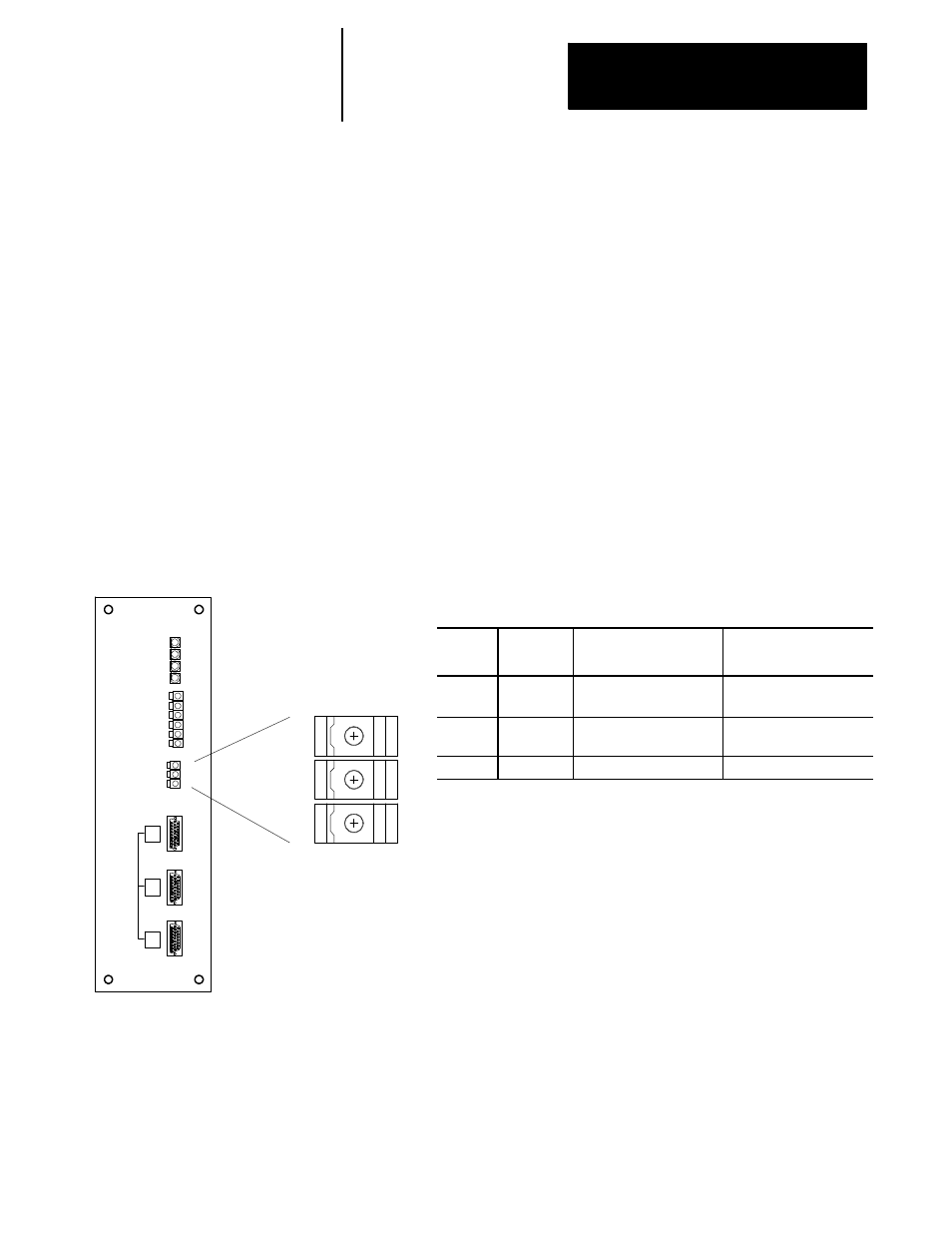
ANALOG OUT (TB2) Auxiliary Output Connector.
An auxiliary analog output is provided through the connector labeled
ANALOG OUT (TB2). This connector is typically used to command an
analog spindle drive system with no position feedback. TB2 is not capable
of receiving encoder feedback information. Figure 4B.31 shows the
location of ANALOG OUT connector and lists terminal assignments of
this connector.
Important: Note that TB2 should only be used for drive applications that do
not require a feedback device. If a feedback is required, the output signal to
the drive and its corresponding encoder feedback should be wired through
one of the axis connectors J1, J2, or J3. A drive application with feedback
would typically not use the connector labeled ANALOG OUT (TB2).
However, if necessary, TB2 may be used with encoder feedback configured in
AMP to be returned to one of the axis connectors J1, J2, or J3.
Figure 4B.31
Terminal Block ANALOG OUT, 3 Plug-type Terminal Block Connections.
Terminal
No.
Signal
Description
Signal Destination
1
Analog Out
+
±
10V Analog with no
feedback
(typically spindle drive)
2
Analog Out
-
Signal Return
(typically spindle drive)
3
Shield
shield
connect at module only