Rockwell Automation 8520 9/Series CNC Integration Maintenance Manual Documentation Set User Manual
Page 372
Section 7A
Connecting Components
7A-24
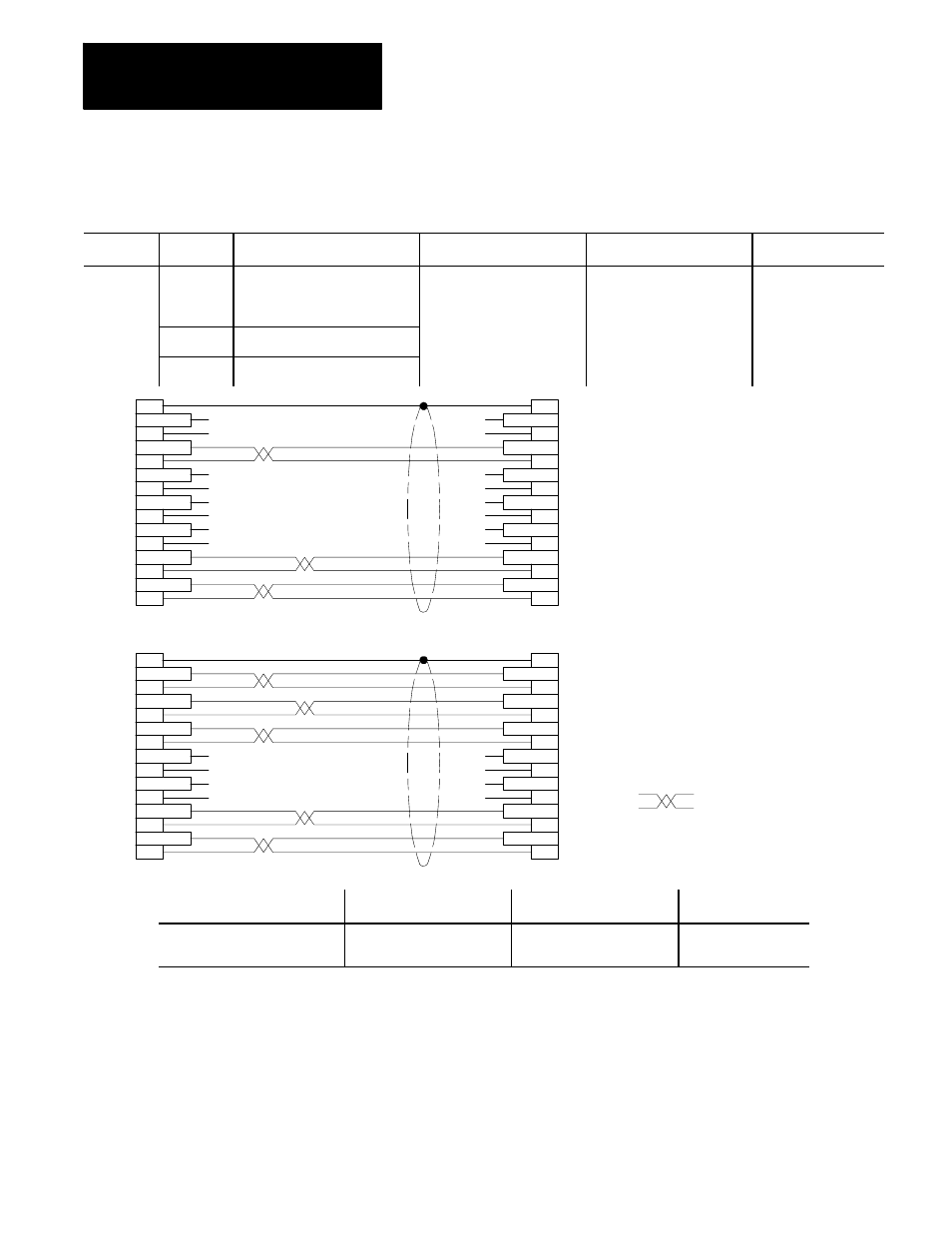
Table 7A.A
Cable and Connector List (continued)
Cable No.
Control
From Module and Connector
Cable Name
To Module and Connector
Cat. No.
C09
9/260 and
9/290
Motherboard J8
Video Signal Cable
CN19M on Operator Panel or
on Portable Operator Panel
Interface Assembly
Prepared by Customer
9/230
Processor Board J8
9/440 (all)
System Module J8
Monochrome
monitor
Color
monitor
Indicates
twisted
pairs
1
2
3
4
5
6
7
8
9
10
11
12
13
14
15
1
2
3
4
5
6
7
8
9
10
11
12
13
14
15
9
10
11
12
13
14
15
9
10
11
12
13
14
15
1
2
3
4
5
6
7
8
1
2
3
4
5
6
7
8
N.C.
N.C.
N.C.
N.C.
N.C.
N.C.
N.C.
N.C.
N.C.
N.C.
N.C.
N.C.
N.C.
N.C.
N.C.
N.C.
N.C.
N.C.
N.C.
N.C.
N.C.
N.C.
N.C.
N.C.
11211-I
Shield (pin 1) on the monochrome
operator panel is not internally
connected to signal common or
chassis ground.
Shield (pin 1) on the color
operator panel is internally connected
to signal common and chassis ground.
gnd (shield)
red (l)
red (h)
green (l)
green (h)
blue (l)
blue (h)
not used
not used
clock (l)
clock (h)
h--sync (l)
h--sync (h)
v--sync (l)
v--sync (h)
shield
rda
rdb
sda
sdb
csa
csb
rsa
rsb
dma
dmb
tra
trb
gnd
rra
shield
rda
rdb
sda
sdb
csa
csb
rsa
rsb
dma
dmb
tra
trb
gnd
rra
gnd (shield)
red (l)
red (h)
green (l)
green (h)
blue (l)
blue (h)
not used
not used
clock (l)
clock (h)
h--sync (l)
h--sync (h)
v--sync (l)
v--sync (h)
Connector On End of Cable
Cable Type
Connector On End of Cable
Max. Cable Length
15--pin D-shell (has pins)
8520-D15M
Belden 9830 (monochrome)
Belden 9832 (color)
15--pin D-shell (has sockets)
8520-D15F
15m (50 ft)