3a.9 wiring a touch probe to the processor module – Rockwell Automation 8520 9/Series CNC Integration Maintenance Manual Documentation Set User Manual
Page 116
TP 5
TP 12
TP 33
TP 7
TP 10
TP 11
TP 13
TP 14
TP 15
TP 21
TP 22
TP 23
TP 24
TP 34
Section 3A
Primary 9/230 Components
3A-33
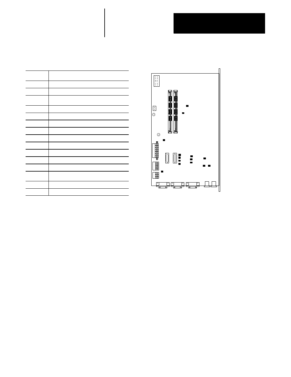
Figure 3A.23
Test Points on the 9/230 Digital
Test Point Analog Out Signal (Spindle)
TP34
DAC Spindle Output
TP33
Analog Output
Test Point Encoder Feedback Signals
TP22
A Channel connector J1
TP23
B Channel connector J1
TP24
Z Channel connector J1
TP11
A Channel connector J2
TP10
B Channel connector J2
TP21
Z Channel connector J2
TP15
A Channel connector J3
TP14
B Channel connector J3
TP13
Z Channel connector J3
Test Point Other Signals
TP5
Digital Ground
TP12
Reset Pin (Connect to Analog GND to Reset)
Connect a touch probe to the connector labeled TP on the processor
module (TB2). Connector terminal identification is provided in
Figure 3A.24. Touch probe cable information can be found on page 7A-1
of this manual.
The time delay between the processor module receiving the touch probe
trigger and latching the current axis position is negligible. However, you
should be aware of any external delays that may introduce position
“staleness” in the probing operation, especially at high probing speeds.
It is a good idea to establish an offset for the distance between the actual
location, as sensed by the probe at a very low speed, and the location
sensed by the probe at the intended probing speed. The offset can then be
added or subtracted to any future values obtained through probing. This
helps make sure that if there are any external delays in the trigger signal,
the position staleness shows up as a constant position offset error and is
removed from the measurement (assuming the external delay is
repeatable).
The motion controller touch probe interface is intended for use with units
that offer 5V dc compatible solid state relay outputs. Other configurations
can be supported as long as the user operates within the published
electrical specifications.
3A.9
Wiring a Touch Probe to the
Processor Module