10a.11 wiring i/o safely – Rockwell Automation 8520 9/Series CNC Integration Maintenance Manual Documentation Set User Manual
Page 589
I/O Interface
Section 10A
10A-66
Many safety issues present themselves to the machine tool builder when
wiring I/O devices. Typically, 9/Series I/O devices attempt to maintain
their current status in the event of a system failure, I/O ring fault, or
E-STOP condition. Make sure that this is a safe state for your machine by
following these guidelines.
Make sure I/O is wired so power failure places the device in a safe
condition. For example if an output point controls an axis brake, you
would typically want the brake applied when the I/O device fails or
loses power.
Make sure I/O is wired so E-STOP condition places the device in a safe
condition. Remember E-STOP conditions do not reset I/O devices. I/O
devices attempt to maintain their last state when E-STOP occurred. For
example if an output point controls an axis brake, you would typically
want the brake applied when the E-STOP condition occurs.
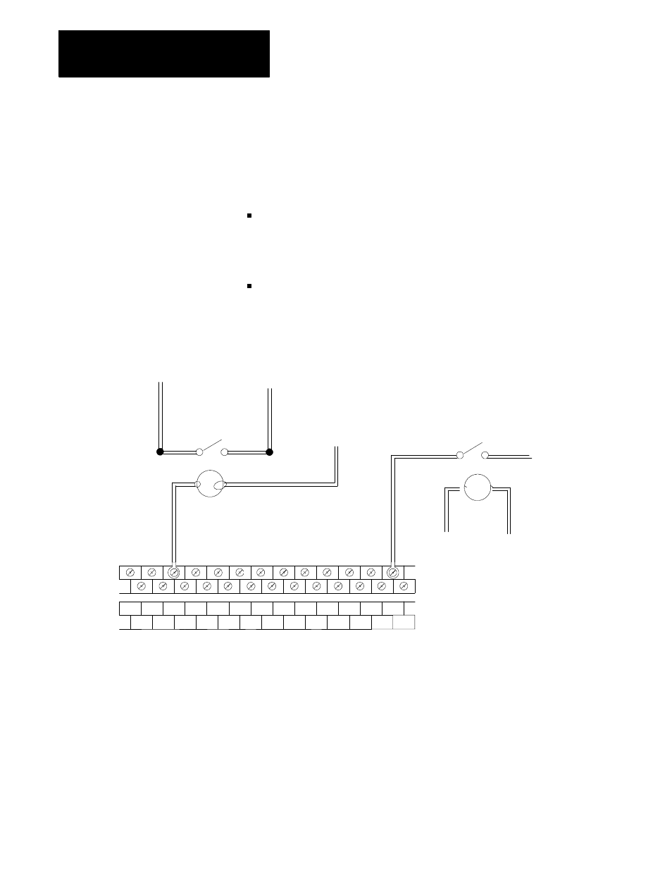
Terminal
Block
Label
COM COM
COM
COM
COM COM
A01 A02 A03 A04 A05 A06 A07 A08 A09 A10
B01 B02 B03 B04 B05 B06 B07 B08 B09 B10
PB2
Customer supplied
brake relay
L2 (L)
R1
R1--1
Brake Circuit
When R1-1 is closed brake
is released.
L1 (H)
Energizes Brake Relay
R2--1
R2
E-STOP String
If E-STOP string is broken, brake is engaged.
Important: Notice in the above figure the E-STOP string only kills power
to the terminal blocks of the I/O module which in turn de-energizes the
brake relay. The actual I/O module on the I/O ring remains powered.
Killing power to the I/O device itself while the fiber optic ring is still
running can cause I/O ring fault errors.
END OF SECTION
10A.11
Wiring I/O Safely