10 mms ethernet communications – Rockwell Automation 8520 9/Series CNC Integration Maintenance Manual Documentation Set User Manual
Page 462
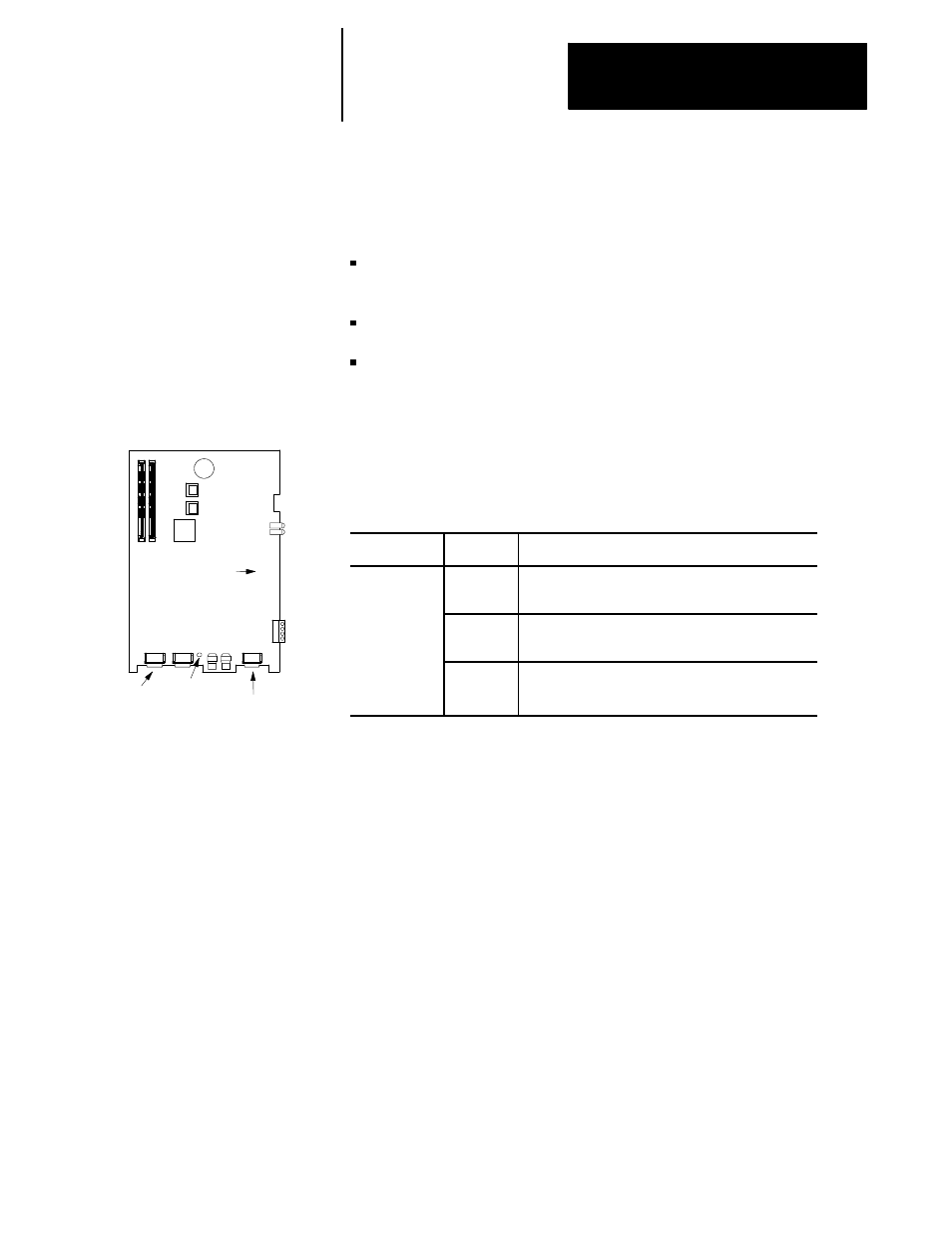
CNC Processor Board
Serial
Port A
Video
Front of
System Module
R--I/O
LED
Section 8
Communication Interface
8-29
9/440 Remote I/O LED
Assuming you have:
made all necessary remote I/O communication connections on your
1771 I/O network
configured your remote I/O port for the remote I/O network in AMP
written PAL to set $RMON true during the first PAL foreground
execution, and to handle input and output words ($RMI1 -- $RMI8
inputs to PAL and $RMO1 -- $RMO8 outputs from PAL.)
You are ready to start receiving and transmitting remote I/O information.
An LED is provided on the 9/440 CNC processor board and is visible from
the bottom of the system module. As remote I/O responds to commands,
you should see this LED pattern:
LED
Status
Description
Green
R- I/O LED
ON
Active Link to PLC. This is the normal state when the
RIO link is active.
FLASHING
The remote I/O link is active but the PLC is currently in
program mode.
OFF
Remote I/O link is offline. The port is not being used,
not configured in AMP correctly, not turned on with
$RMON, or not attached to a 1771 device.
The 9/260 and 9/290 CNCs have an MMS Etherent communications
module available that provide MMS Ethernet services. With this module,
the software is pre--installed with a set of default communication settings
(modifications to these defaults is performed with Allen-Bradley Station
Manager software).
A wide range of services are supported that allow you access to PAL and
control variables, part program management, CNC status, etc... Details on
the MMS Ethernet communications module are provided in a separate
9/Series MMS/Ethernet Communication Module Users Manual (Catalog
number 8520-ENETM). Refer to this publication for further details.
8.10
MMS Ethernet
Communications