Input interface ribbon cable, Output interface ribbon cable – Rockwell Automation 8520 9/Series CNC Integration Maintenance Manual Documentation Set User Manual
Page 496
Section 9A
Operator Interface
9A-29
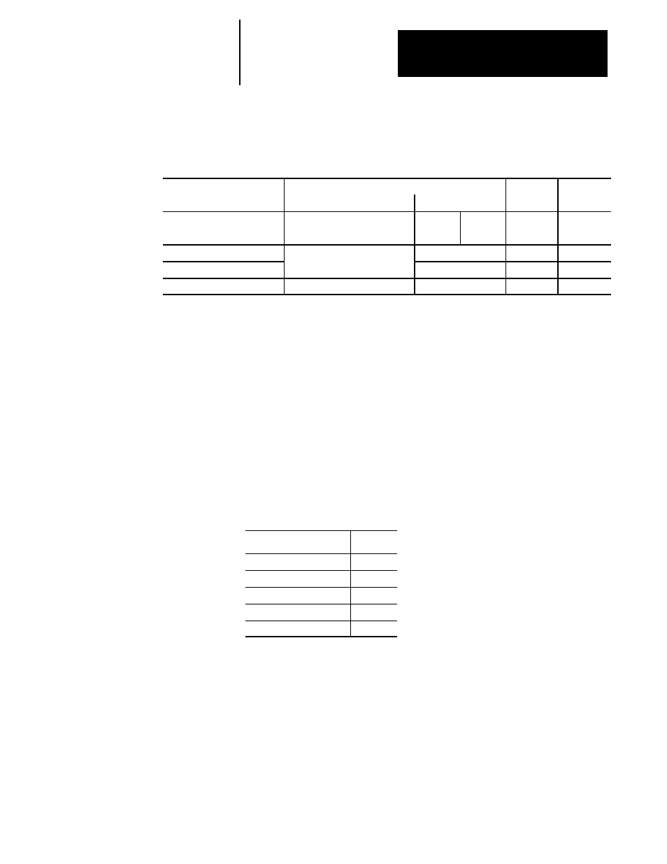
Table 9A.K shows additional connectors of the push-button MTB panel.
Table 9A.K
Push-Button MTB Panel Connectors
Connector On
Connected To
Cable
Remark
Push-Button MTB Panel
Component
Connector
Number
+12V
Operator Panel
+12V
GND
Power Supply
BT03
GND
C28
Input Interface Ribbon Cable
Standard MTB
CN51
C26
Input
Output Interface Ribbon Cable
Panel I/O Module
CN52
C27
Output
CN56F
Motherboard/System Processor
CN16F
C07
Port B
Input Interface Ribbon Cable
Input signals from the push-button MTB panel are sent through input
interface ribbon cable to connector CN51 on the push-button MTB panel
I/O module. These signals are then sent to the motherboard via the fiber
optic I/O ring. Table 9A.L shows the pin assignments and functions for
input interface ribbon cable on the push-button MTB panel.
PAL expects the push-button MTB panel input signals, which are shown
below, to be sent through the push-button MTB panel I/O module on the
corresponding pin numbers. If the input signals differ from those listed in
Table 9A.L, the PAL I/O assignments file must be altered. Refer to the
9/Series CNC 9/230,9/260, and 9/290 PAL Reference Manual, publication
8520-4.3, for more information.
The default settings at power-up for the push-button MTB panel are:
Selection
Default
Mode Select
MAN
Jog Select
CONT
Speed/Multiply
X1
Spindle
OFF
Rapid Feedrate Override
F1
Output Interface Ribbon Cable
Output signals from connector CN52 on the push-button MTB panel I/O
module are sent to the push-button MTB panel via the output interface
ribbon cable. Table 9A.M shows the pin assignments and functions for
output interface ribbon cable on the push-button MTB panel. PAL outputs
signals to the push-button MTB panel through the push-button MTB panel
I/O module on the corresponding pin numbers. If the output signals differ
from those listed in Table 9A.M, the PAL I/O assignments file must be
altered. Refer to the 9/Series CNC 9/230, 9/260, and 9/290 PAL Reference
Manual, publication 8520-4.3, for more information.