Rockwell Automation 8520 9/Series CNC Integration Maintenance Manual Documentation Set User Manual
Page 794
Section 15B
Replacement Procedures
15B-38
3.
Loosen the four screws holding the battery pack to the control
chassis.
4.
Replace the old battery pack with a new one and tighten the four screws.
5.
Connect the new battery pack to connector CN10 on the 3-axis servo
module or connector P3 on the 4-axis servo module.
6.
Turn ON power to the control.
Batteries and battery replacement instructions are included with the battery
replacement kit. Before installing new batteries, use a voltage meter to
make sure that new battery voltage is higher than 3.5V.
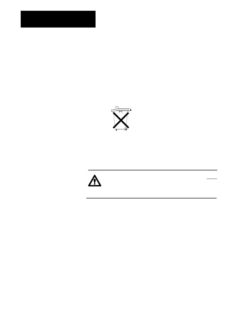
The lithium battery contains heavy metals and
must be collected separately from other waste.
This is not available on the 9/230 control. To replace the digital servo
module:
1.
Turn OFF all power to the control.
ATTENTION: To guard against electrical shock hazards, never
make connections or disconnections at the ac distribution
network unless the main ac disconnect switch is open and
locked.
Important: The use of a ground strap is recommended to prevent static
discharge.
2.
Disconnect all cables that are connected to the servo module.
Important: The control must be “homed” after replacing the servo
module. If the servo motors incorporate an absolute encoder, the absolute
axis position will be lost. The absolute encoder must be reset after the
servo module is replaced. Refer to page 13A-33 for absolute encoder reset
procedures.
3.
Remove the 4 mounting screws that hold the board rack, which holds
the servo module to be replaced, in the component enclosure. Slide
the board rack out of the component enclosure board slot.
15B.23
Replacing the 3-axis
Digital Servo Module