Assigning a module address – Rockwell Automation 8520 9/Series CNC Integration Maintenance Manual Documentation Set User Manual
Page 483
Section 9A
Operator Interface
9A-16
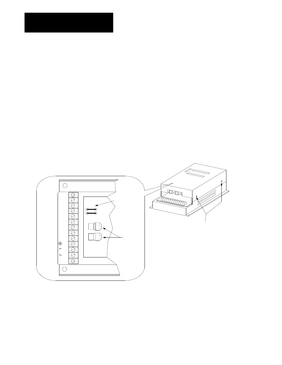
Assigning a Module Address
Each interface assembly must have a unique node address on the I/O ring.
The node address corresponds to a unique address assigned as independent
operator panels in the I/O assignment file found in ODS (see your PAL
reference manual). The node address is selected by cutting the jumpers
located on the interface assembly(s). Figure 9A.10 shows the location of
the jumpers on the interface module.
Important: You must remove the cover from the removable operator panel
interface assembly to access the node address jumpers. Turn off power to
the interface assembly before removing the cover. Make sure to follow
proper ESD grounding procedures when working on any 9/Series
equipment.
Figure 9A.10
Removable Operator Panel Interface Assembly JP1 and JP2
Jumper Locations
Remove cover
(2 screws each side)
G
ND
12V
G
ND
5V
G
ND
5V
G
ND
5V
AC
JP1
JP2
Fiber Optic
Connections
Jumpers
L2
L1
PE
Set the node address by cutting the wire jumper(s) according to
Table 9A.E.
The node address may be any number between 00 and 03. You may have a
total of 4 interface assemblies in the 9/Series fiber optic I/O ring. The
same node address can be used for other types of modules however, each
removable operator panel interface assembly must have its own unique
address.